I haven't checked, but you may find a triac cheaper and easier to source than a high-voltage rated FET. Use an opto-triac (MOC3020 or similar) to trigger a power triac. Then you can use DC (either polarity) to drive the opto's LED.
what is the difference between Maximum Gate Trigger Current and Surge Current Rating ? how to know current gate that will hold?
also what is the difference between "Triac logic level" and Sensitive Gate Triac" ? which of them suits my app.?
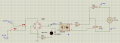
i attached the circuit , i want your comments. i postulated that the load resistance is 50 ohm
Maximum Gate Trigger Current seems to denote two things, depending on which datasheet is used. If listed under Maximum Ratings, it means the highest current you can pass through the gate without damaging the triac. If listed under Electrical Characteristics it means the highest current needed to guarantee the triac will trigger.
Surge Current Rating means the maximum current allowed briefly, under certain specified conditions, e.g. one full cycle at 60Hz.
A sensitive gate type would be preferred in your application, IMO.
BTW, R3 needs to be increased to avoid frying the opto-LED. 400 Ohms wold allow ~50mA to flow!
Surge Current Rating means the maximum current allowed briefly, under certain specified conditions, e.g. one full cycle at 60Hz.
BTW, R3 needs to be increased to avoid frying the opto-LED. 400 Ohms wold allow ~50mA to flow!
As the datasheet says, "Peak Non-Repetitive Surge Current (One Full Cycle Sine Wave, 60 Hz,TC = 25°C) 250A".
In other words, you are allowed to pass 250A (e.g. at start-up when charging a fat capacitor), but only for one cycle of a 60Hz mains supply. For continuous use the maximum safe current is 25A (which would probably require use of a massive heatsink). It is not good practice to run any electronic component at or close to its maximum rating.
what is the maximum input voltage on the optoisolator ? should it be the forward voltage that is 1.4v in datasheet?
if i want to use triac without heat sink at 20A should i increase maximum rating current to 40 A? will that be ok.?
It's not so much the input voltage as the current through the opto-diode that matters and must be kept below the rated maximum (which I haven't checked). LEDs need to be current-driven, not voltage-driven. Often only a few mA are needed for an opto. What the datasheet is telling you is that at the rated current the diode forward voltage will be no more than 1.4V (I just guessed 1.5V in post #28).
If i want to use triac without heat sink at 20A should i increase maximum rating current to 40 A? will that be ok.?
I very much doubt it. If we assume, for argument's sake, the triac (whatever type) drops 1V when 'on', then at 20A it will have to dissipate 20W. It will get very hot!! Use a heatsink.
I thought you said your load would be 50 Ohms? That would draw < 5A. Where did you get the 20A figure?
If it really will be 20A then perhaps a FET as you originally proposed would be better than a triac from a power dissipation viewpoint. Perhaps something like this? But an SSR would likely be a better solution.
Shouldn't everything on the high voltage side of the opto-isolator be high voltage? I'm assuming the mystery 24v feeding through the opto and into the gate is probably the same 24v used to power the microcontroller and therefore also the the low voltage side of opto. If this is true, it would make the opto redundant and useless because component failure could easily connect high voltage through the 24v line to the microcontroller, creating a very unsafe situation.
Please correct me if I'm wrong. Haven't actually used optos myself yet but I have some projects in mind and I want to make sure I'm understanding their application correctly. Thanks!
(When the time comes, I'll definitely post what I'm considering on these forums before trying anything involving high voltage risks. Safety first!)
I thought you said your load would be 50 Ohms? That would draw < 5A. Where did you get the 20A figure?
If it really will be 20A then perhaps a FET as you originally proposed would be better than a triac from a power dissipation viewpoint. Perhaps something like this? But an SSR would likely be a better solution.
We still don't know whether you are trying to switch 20A or <5A
Did you check the FET in my post #31 link? That has a rated Rds(on) of 78 milliOhms, so at 5A and 20A would dissipate ~0.4W and 1.6W respectively [Edit: see post #39 for correction]. Even 0.4W would probably require a small heatsink.
I suggest you do a parametric search of FET vendor sites for a lower Rds(on) type, but with a Vds rating > 500V.
i am trying to switch 20A . i will search of fet but i need your practical recommendations for the architecture of the circuit.
i think that you mean the dissipated power in 20A will = 20x20x0.078=31.2 watt
Don't forget the bridge rectifier devices also running at 20 amps with a combined forward drop of at least 1.4 volts adding another 28+ watts of heat to get rid of.
 Facebook
 Google
 GitHub
 Linkedin