Facebook
 Google
 GitHub
 Linkedin
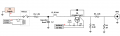
I have a surge tester setup that uses a high-voltage power supply (up to 1000 V) to charge a non-polarized capacitor bank using SW1 to energize Relay 1 in Image 1. The bank discharges into a waveshape network (inductors + resistors) through a high-power relay, triggered by a push-button. Each activation generates a pulse with a 30–40 us rise time and 100–140 us fall time. See Image 1 for the current relay circuit.
The total series impedance is ~1 ohm, so the open-circuit voltage approximates the short-circuit current when the output is shorted to the bench ground. The supply supports both positive and negative output voltages, and the non-polarized capacitors allow generation of both positive and negative polarity pulses (voltage and current).
I’m looking to replace the mechanical relay (relay 2 in Image 1) with a solid-state switch, as repeated high-voltage/current cycles are causing contact sticking. I’m seeking recommendations on the most suitable switch type (IGBT, MOSFET, etc.), particularly for bidirectional operation.
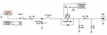
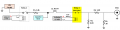
Image 2 shows an initial concept using a high-power IGBT for positive polarity pulses. However, IGBTs are unidirectional, and I’m unsure how to support negative pulses. Would reversing the IGBT and referencing the gate drive to the high-side emitter work for negative polarity? gate to emitter reference will break with the high voltage at the emitter side. If there's a better topology or practical solution that still supports push-button triggering and an isolated supply, I’d appreciate any guidance.
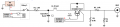
I’ve also identified a bidirectional IGBT module that appears suitable for my power levels.
https://www.infineon.com/dgdl/Infin...N.pdf?fileId=8ac78c8c869190210186e5fa2b4e6c24
The total series impedance is ~1 ohm, so the open-circuit voltage approximates the short-circuit current when the output is shorted to the bench ground. The supply supports both positive and negative output voltages, and the non-polarized capacitors allow generation of both positive and negative polarity pulses (voltage and current).
I’m looking to replace the mechanical relay (relay 2 in Image 1) with a solid-state switch, as repeated high-voltage/current cycles are causing contact sticking. I’m seeking recommendations on the most suitable switch type (IGBT, MOSFET, etc.), particularly for bidirectional operation.
Image 2 shows an initial concept using a high-power IGBT for positive polarity pulses. However, IGBTs are unidirectional, and I’m unsure how to support negative pulses. Would reversing the IGBT and referencing the gate drive to the high-side emitter work for negative polarity? gate to emitter reference will break with the high voltage at the emitter side. If there's a better topology or practical solution that still supports push-button triggering and an isolated supply, I’d appreciate any guidance.
I’ve also identified a bidirectional IGBT module that appears suitable for my power levels.
https://www.infineon.com/dgdl/Infin...N.pdf?fileId=8ac78c8c869190210186e5fa2b4e6c24
Attachments
-
 19 KB Views: 14
 -
 27.9 KB Views: 14
Last edited: