It will give me a chance to make your have the best shot at a nice outcome. I might have one other idea, too. Which doesn't involve a switch at all, at least not one that you buy. But I have to try something first.
When you see this, please get me some photos of the housing the button part goes in. I have found a couple of possible ways of centering the switch under the button and connecting it electrically, but they are all pretty fiddly and will take some soldering skill. I don't know how confident you are soldering small parts, how do you feel about that?
OK, so here's the idea. I roughly simulated your PCB geometry and this seems to work:
What I've done is to trim the leads marked with the yellow X, bend the top lead to cut across the top of the teardrop and the bottom lead to reach the pad in the corner, though if reaching the round section is easier, that's fine. I used very fine solder and applied some flux to make thing wet more quickly. Just be careful about overheating. If your iron has a temperature control, set it to 315°—335°C. You should get some 63Sn/37Pb solder so you can keep the heat down and not fight with cold joints.
Mechanically, it feels very solid. But a drop of cyanoacrylate cement on the bottom might help reinforce that, and make it easier to solder since it will stay in place. Don't overdo the glue, literally just a small drop. If you manage to get is stuck in the wrong place, or need to start over with a new switch, don't brute force it off. A couple of drops (not more) of acetone will get it off.
Let me know if you have any questions. This is not easy but it's not brain surgery either. If you have some old PCBs or something you can practice on, do a dry run it doesn't matter if it's identical. Get a sense of how much solder and how much heat. When you feel confident, try it.
When you see this, please get me some photos of the housing the button part goes in. I have found a couple of possible ways of centering the switch under the button and connecting it electrically, but they are all pretty fiddly and will take some soldering skill. I don't know how confident you are soldering small parts, how do you feel about that?
I am pretty confident with small soldering. I have the flux and solder but not sure how fine the wire is. I have a Hakko 888 the analog one. I can set the temp as required. It is going to take a while to get the switches. I like the layout you made.
What I've done is to trim the leads marked with the yellow X, bend the top lead to cut across the top of the teardrop and the bottom lead to reach the pad in the corner, though if reaching the round section is easier, that's fine. I used very fine solder and applied some flux to make thing wet more quickly. Just be careful about overheating. If your iron has a temperature control, set it to 315°—335°C. You should get some 63Sn/37Pb solder so you can keep the heat down and not fight with cold joints.
Mechanically, it feels very solid. But a drop of cyanoacrylate cement on the bottom might help reinforce that, and make it easier to solder since it will stay in place. Don't overdo the glue, literally just a small drop. If you manage to get is stuck in the wrong place, or need to start over with a new switch, don't brute force it off. A couple of drops (not more) of acetone will get it off.
Let me know if you have any questions. This is not easy but it's not brain surgery either. If you have some old PCBs or something you can practice on, do a dry run it doesn't matter if it's identical. Get a sense of how much solder and how much heat. When you feel confident, try it.
The main thing I didn't know is how big the switch body was. It looks like it fits and the switch leg to an oval pad or the 1/4 moon part looks like it reaches too. Yeah! thank you! I can't wait for the switches to come in. i will have a few extras.
When you see this, please get me some photos of the housing the button part goes in. I have found a couple of possible ways of centering the switch under the button and connecting it electrically, but they are all pretty fiddly and will take some soldering skill. I don't know how confident you are soldering small parts, how do you feel about that?
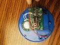
The pic of the button plunger is the housing. Do you want another angle? the blue part is a ring that the big black button with the plunger part is captured by. It all screws together.
The pic of the button plunger is the housing. Do you want another angle? the blue part is a ring that the big black button with the plunger part is captured by. It all screws together.
No, it's OK.I went by your measurements so you will have to see how closely it fits what it's like when you test the switch positioning. I think there is enough slack that it should work in any case.
No, it's OK.I went by your measurements so you will have to see how closely it fits what it's like when you test the switch positioning. I think there is enough slack that it should work in any case.
No, it's OK.I went by your measurements so you will have to see how closely it fits what it's like when you test the switch positioning. I think there is enough slack that it should work in any case.
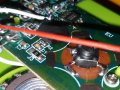
Yaakov, The switches arrived! It looks like they will fit fine. I believe because of the way it functions as a button not like the dome switch where it had to bottom out to make contact, the switches will work great.
I checked continuity and found the 2 common pairs. Your picture helped so much with how these work electrically! I will solder this on Saturday.
I have AMTECH flux. I have 0.032 but I think I have some 0.015 63/37. It might be organic. I am not sure the difference or benefits. I kow that AMTECH flux made feel like a pro. I didn't know there was that big a difference in flux!
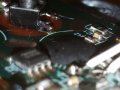
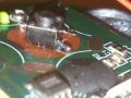
Yaakov, would you mind looking at the solder joints and tell me if they look like they will hold up? I am an amateur, be gentle lol.. I found a switch that was DOA and practiced on it and have no idea if it works. Crazy thing is record button works, it beeps telling you it is recording so speaker works? and then tried the hard wire to verify it had same pads for the switch and it didn't playback. This green 1 never has.
If the solder joints look good I am ready. Thank you for the help!!
Yes. I practiced on this one. Physically the button stays put. I was worried about hurting the pads, do I need to heat them like I would 2 wires or will they get hot enough thru the iron contact with switch legs and flux? I tested the continuity between the pads... all good, and activating the switch completes the circuit on any pad. I picked up and shook the device by the switch and it held.
I do not know why it didn't work before but not worried, 1 thing at a time. I got 4 in the box and this was DOA. Since the record button activates and beeps indicating it is recording and the speaker Beeps so it is working, the button switch functions, I would think maybe the microphone is not working or the memory for the recording is bad. If I can make the others work I am happy.
If the solder "wets" the pads and flows everything is good. Solder actually alloys with the metal you solder to. The wetting action happens when the alloy is formed and you can't do better than that.
You can "tin" the pads first to make things easier. Just put a small amount of solder on the pad where you will connect to it. You want just enough to color the pad silver because you will have trouble positioning the switch if you make a lump. Clean the iron thoroughly so thee is no solder on it, them put the iron on the pad, then touch the solder directly next to the iron until a very small amount melts and wets the surface. It sometimes helps if to touch the tip momentarily and pull away to start the melting.
If your iron has a termoerature control, set it to about 320°C, it doesn't need to be hotter. Don't worry about the pads, you would have to severely overheat them to lift them. If you have trouble getting joint to form and have the iron in place more than 3 seconds or so, stop, remove the iron and let the pad and switch cool for at least 10 seconds, clean the tip, and try again.
Knowing how hot to set my iron is a big help. I think I have made it over heated in the past. I use Hakko FS-100 solder tip cleaning paste if tip looks bad. The joint hold when I tug test it.
Knowing how hot to set my iron is a big help. I think I have made it over heated in the past. I use Hakko FS-100 solder tip cleaning paste if tip looks bad. The joint hold when I tug test it.
The datasheet for the solder you are using will tell you the temperature you should set. It's usually specified as a small range. Sometimes a bit on the hotter side is better since it reduces heating time and get the local region hotter faster.
Tip cleaner is great, but oyu only need it if you using the bronze wool doesn't do a good enough job. I don't suggest using a sponge, if you do. It doesn't work better than the wool, it cools the tip, and some suggest it could cause the plating to deteriorate more quickly from stress fractures. I don't know the validity of the last, but it is certainly no more effective than the wool and much more hassle.
If you want to get really nerdy about it, pick up one of these. It will allow you to calibrate your iron so the displayed temperature is the actual temperature. It is a copy of the Hakko FG-100 which is ~$270.00. It's not a counterfeit since it isn't labeled Hakko, though those do exist. It will be more than good enough for the 20 bucks to get your iron in spec considering your application, and, I find it very satisfying to know my display is actually the tip temperature for all intents and purposes I could have.
 Facebook
 Google
 GitHub
 Linkedin