replace mechanical switch

Thread Starter

Hondoman

Joined Feb 21, 2022
28
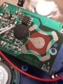
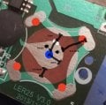
Hello I am new to the forum. I am trying to modify a button switch for a special needs child. It is hard to press the 3" button and I thought about using a MX Cherry switch instead. I see it comes with a metal housing or pins, not real sure what that would require but I want it to be durable. The current set up has a metal square that "bends" to activate and that is too hard, connects at 4 points on the board and a pic is included with pencil pointing to the metal square switch it has now. It is too resistive for our child to push. The MX data sheet looked promising for 2.1-3oz pressure. I think the tactile feedback Brown may be best. The clicky with tactile and sound may be better and I want to modify 3 switches to try out what works best. They all seem to have about the same force 2.1 up to 3oz.
If anyone would like to help me I would be grateful. I do not have much electronic background, a little Arduino projects but know how to solder and was an electrician. The switch states works with 12vdc to 2vdc range but it's a switch right?, will the AA battery not be enough power? I do not need the LED, but it would be nice, no need to complicate things more at this point. I hope this is the best place to get help on this issue, if not can someone recommend a site?
Thank you in advance.
 

Attachments

Ya’akov

Joined Jan 27, 2019
9,079
Welcome to AAC.

The switch you are trying to replace is a very simple one so it should be electrically easy to do. They are called dome switches and they operate by making a connection from the outside solder pads to an invisible inner one (under the dome).

There is not always an electrical connection to all four "legs" but in your case, from the photo, there seems to be.

The first step will be to desolder the dome. You will find a pad underneath, in the center. Test by using a short wire to connect one of the leg solder pads to it momentarily. If it works, the job is trivial electrically and your problem will be mechanical, how to mount it.
 

Ya’akov

Joined Jan 27, 2019
9,079
I don't know if this is helpful, but here's a picture.

Pull off the foam or it will melt and burn and make a mess.
The desoldering be careful not to overheat the board.

You can use something like a small screwdriver to lift up on the dome using one of the gaps you will see when the foam is gone. The idea is to lift one leg at a time as soon as the solder allows it. You can't melt all four at once. Prying will work, but be gentle, once the solder melts very little force will be needed.

1645546655607.png
 

Thread Starter

Hondoman

Joined Feb 21, 2022
28
Thank you for your help. As I took the foam off it was stuck to tape, that was all that was holding the dome switch. Do the pics show the circuit? There is a big black blob, right from the center contact out to it. I do not really see the layout? I mean I have replaced the incandescent bulbs with LEDs in my steering wheel controls of my car but it was obvious, the trace is that all the green part?
Next I need to make contact with a wire from the center to find the one that activates it right?
 

Attachments

Ya’akov

Joined Jan 27, 2019
9,079
Thank you for your help. As I took the foam off it was stuck to tape, that was all that was holding the dome switch. Do the pics show the circuit? There is a big black blob, right from the center contact out to it. I do not really see the layout? I mean I have replaced the incandescent bulbs with LEDs in my steering wheel controls of my car but it was obvious, the trace is that all the green part?
Next I need to make contact with a wire from the center to find the one that activates it right?
Sorry, I should have known the dome would be taped down, that's to allow movement. Connect the switch to any one red point and the blue point. you can test it with a wire instead of the switch.

1645548632234.png
 

Thread Starter

Hondoman

Joined Feb 21, 2022
28
It was just delayed. I am using a piece of phone wire I had available and it takes a second, not instant response.
I was looking at the low profile but I will have to modify the button plunger anyway. The low profile data sheet show 45 cN force and that converts to 1.61 oz force. That was part of the issue that she couldn't push it down easy to activate it.
 

Attachments

Thread Starter

Hondoman

Joined Feb 21, 2022
28
Thank you again Yaakov. Making progress. The data sheet says 12vdc or 12vac but is that the limit or what it requires to operate. I have 2 AAA batteries for power?
Now comes the fun part, mounting it.
I have not purchased the MX switches. They seemed like a good choice. Know of any better options for this application?
I will check back later. Cheers.
 

Ya’akov

Joined Jan 27, 2019
9,079
Thank you again Yaakov. Making progress. The data sheet says 12vdc or 12vac but is that the limit or what it requires to operate. I have 2 AAA batteries for power?
Now comes the fun part, mounting it.
I have not purchased the MX switches. They seemed like a good choice. Know of any better options for this application?
I will check back later. Cheers.
The switch specifications are maximum ratings, not requirements. It will do the switching part for you without a problem. You might find that an common tactile switch switch is simpler to adapt, here is the force table from a datasheet for a common type.

1645552475162.png
1N (Newton) is about 3 ounces. These are cheap and readily available. I just tested a few different types I have here and the ranged from 9 ounces down to 5 ounces. You could try buying this assortment, which includes a variety of actuator lengths which might make it easier to adapt. to the existing button. The idea would be to fold the leads out flat and solder them to the center and maybe even one of those partial round sections near the middle, that is part of the same circuit as the pads.

1645553430326.png
If you can just replace the dome with something easier and not have to modify anything else that would be a win.
 

Thread Starter

Hondoman

Joined Feb 21, 2022
28
Thank you. Just replace the dome is my current goal, less is more! absolutely.
I will look at these, the price/unit is right!!
I tested and yes the outer 1/4 moon areas activate it like the oval pads. It's about 1/4 inch from center to an outer moon and 3/8 inch out center to oval pad. Do you have those switches to see what spread distance the legs provide?
The height is easy to trim for the button plunger. The dome switch is very thin even with the foam maybe < 3/16".
Thanks you so much for the help. I kept falling into rabbit holes searching for a fix.
 

Attachments

Ya’akov

Joined Jan 27, 2019
9,079
Thank you. Just replace the dome is my current goal, less is more! absolutely.
I will look at these, the price/unit is right!!
I tested and yes the outer 1/4 moon areas activate it like the oval pads. It's about 1/4 inch from center to an outer moon and 3/8 inch out center to oval pad. Do you have those switches to see what spread distance the legs provide?
The height is easy to trim for the button plunger. The dome switch is very thin even with the foam maybe < 3/16".
Thanks you so much for the help. I kept falling into rabbit holes searching for a fix.
When I get home, I’ll measure for you.
 

Ya’akov

Joined Jan 27, 2019
9,079
Thank you. Just replace the dome is my current goal, less is more! absolutely.
I will look at these, the price/unit is right!!
I tested and yes the outer 1/4 moon areas activate it like the oval pads. It's about 1/4 inch from center to an outer moon and 3/8 inch out center to oval pad. Do you have those switches to see what spread distance the legs provide?
The height is easy to trim for the button plunger. The dome switch is very thin even with the foam maybe < 3/16".
Thanks you so much for the help. I kept falling into rabbit holes searching for a fix.
So, it's 15mm diagonally across the flattened legs. I know that's odd but the first figure shows (too much at once) how the connections are made. The dashed red line show how the legs are electrically common, the black switch symbol shows how they are switched. The second figure shows how you could bend the legs (carefully) for a more mechanically sound connection but you loose 3.5mm in length.

1645638635445.png
figure 1

1645638696366.png
figure 2
 

Thread Starter

Hondoman

Joined Feb 21, 2022
28
The illustrations are so helpful! Thank you.
The snow cone shape center is 6.5-7mm widest and about 3mm from center to edges. Will the switch fit over that and I can drill holes??? for those pins and extend out for the moon side or will that damage board? it looks like a single layer. It is about 3.5-4mm from snow cone edge to 1/4 moon and 6.5-7mm to the oval pad.
I am looking at it and thought maybe holes in center conductor, but not sure if 2 legs with crab bend will reach to the 1/4 moon. The orientation part I am unsure about.
 
Last edited:

Ya’akov

Joined Jan 27, 2019
9,079
I can't quite picture what you are talking about but my first expectation was that you would surface mount the switch. Could you mark upon the photo of the board with some dimensions? That would help.
 

Thread Starter

Hondoman

Joined Feb 21, 2022
28
I can try, I don't have good software for pic editing... Your anotations are great!
I only have Windows paint program, sorry but hope it comes out.
So I was thinking of drilling holes in the center pad where those black dots are, and not sure if the other switch legs will reach the outer points. I can't tell how big the switch is and if it was centered on the blue dot, will those other legs reach the 1/4 moon area or the oval pad?
 

Attachments

Ya’akov

Joined Jan 27, 2019
9,079
I can try, I don't have good software for pic editing... Your anotations are great!
I only have Windows paint program, sorry but hope it comes out.
So I was thinking of drilling holes in the center pad where those black dots are, and not sure if the other switch legs will reach the outer points. I can't tell how big the switch is and if it was centered on the blue dot, will those other legs reach the 1/4 moon area or the oval pad?
OK, I will give you a plan, but I can't do it tonight, so I will write something up tomorrow to explain it.
 

Thread Starter

Hondoman

Joined Feb 21, 2022
28
I would surface mount it at least the 2 legs to the outer contacts and then through hole the other 2 for durability. I can surface mount all of the legs, I don't know how big the switch body is, do I just cut the legs short so 2 stay inside the center pad.
I just read your post ok. I know this is a probably a trivial thing, I just have no experience. I know what I want to do and what contacts need to be made, just not how big the switch is or the leg length from switch body edge.
Thank you for your patience, and please know this will help a very special person. Bless you.
 

Ya’akov

Joined Jan 27, 2019
9,079
Would it be OK with you if I got something to you on Sunday? I want to make sure it is detailed and clear, and tested if possible and I don't have enough time in a row to concentrate on it today.
 
Top