I don't understand that statement isn't that what should be the case?
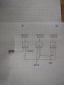
For clarity this is the wiring required using that 4 channel relay module minus the contacts.
Do you mean the rest of the relays on that 4 channel module?
If so, they all can be operated from either grounding the input or connected to a positive voltage depending on the setting of the jumpers.
Otherwise it's working for you?
well that was short lived,something burnt up in the shift light circuit. Do you think I should buy another one or try to build to suit my needs.The one I bought was a cheap ebay $20. After doing some research it looks like the LM 2917 might be a starting point also.
For some back ground on what I'm trying to do: I have a Honda Ridgeline that I swapped out the automatic transmission with a manual transmission and I need the ecm to function as if the automatic was still being used. Mechanically it works fine,but to keep from getting check engine light I need to come up with a fix. Using the relays works fine but I wanted to add the shift light function to go from being in neutral(grounding the neutral wire at the ecm) up to around 2500rpm and then switching to 2nd gear(switching the ground from neutral to 2nd). Any suggestions are welcome. Thanks
Why do you think that module burned up? How is it connected in the truck?
Wasn't it working fine before connecting to the relay module?
Post a link to this shift light module please.
The module only has .3 volts on both legs and the board itself is very hot.I just had a jumper wire on the negative leg to the relay board.Its hooks to the truck with 12v wire and a single wire that goes to the tachometer output on the ecm.Ill try and send a link for it but it's a cheap shift light from amazon or ebay
Not much to say about the module.
"The module only has .3 volts on both legs and the board itself is very hot"
What do you mean by .3 volts on both legs?
If interested in making a circuit this speed switch should work.
The values for C1 and R4 depend on the actual frequency of the Tach Output from the ECU at 2500 rpm.
If you would like to try building your own circuit I think this should work using a LM2907.
The values for C1 and R4 depend on the actual frequency of the tach output at 2500 rpm.
Need to measure the frequency of the tach output when the engine is at 2500 rpm.
Do you have a meter with a frequency function?
It might simply be 2500/60= 41.67 hz.
Can start from there and see if that works.
C1 = 100nf
R4 = 120K
Added a LED for visual indication when testing.
 Facebook
 Google
 GitHub
 Linkedin