 Facebook
 Google
 GitHub
 Linkedin
Hey All,
I am following directions from the link below to build a remote control kill switch using a pair of walkie talkies. It uses a 741 op amp to activate an automotive relay and the op amp is activated via the receiving walkie talkie.
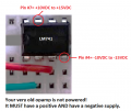
Attached is a picture of my schematic and my problems are as follow;
- According to the directions, when the output of the receiver(going to pin #3 of Op Amp), goes above the reference voltage (pin #2) the output pin(#6) of the Op Amp goes "high." I have successfully calibrated the resistance so that the reference voltage at pin #2 is always .5 VDC. I have the receiver successfully sending 1.8VDC to pin #3 HOWEVER the output pin #6 only reads between 1.3 and 1.4 VDC.
- After that point the signal is supposed to go to a MOSFET transistor, I didn't have one so I put a BJT instead. But honestly I haven't read that far ahead because I'm not getting a "HIGH" signal from the output of the 741 op amp..........if the output of the 741 is less than the input coming from the receiver what's even the point of it???? Right? lol
Instead of using the op amp and all, can't I just build a basic amplifier circuit that would boost the 1.8VDC to 12VDC in order to activate the car relay? If this is the way to go, does anyone have any schematics I should refer to? Why isn't the op amp doing what it is said to do in the instructions? Any help would be greatly appreciated!
Thank you!
Link to the original online directions; https://www.instructables.com/Remote-Kill-Switch/#discuss


I am following directions from the link below to build a remote control kill switch using a pair of walkie talkies. It uses a 741 op amp to activate an automotive relay and the op amp is activated via the receiving walkie talkie.
Attached is a picture of my schematic and my problems are as follow;
- According to the directions, when the output of the receiver(going to pin #3 of Op Amp), goes above the reference voltage (pin #2) the output pin(#6) of the Op Amp goes "high." I have successfully calibrated the resistance so that the reference voltage at pin #2 is always .5 VDC. I have the receiver successfully sending 1.8VDC to pin #3 HOWEVER the output pin #6 only reads between 1.3 and 1.4 VDC.
- After that point the signal is supposed to go to a MOSFET transistor, I didn't have one so I put a BJT instead. But honestly I haven't read that far ahead because I'm not getting a "HIGH" signal from the output of the 741 op amp..........if the output of the 741 is less than the input coming from the receiver what's even the point of it???? Right? lol
Instead of using the op amp and all, can't I just build a basic amplifier circuit that would boost the 1.8VDC to 12VDC in order to activate the car relay? If this is the way to go, does anyone have any schematics I should refer to? Why isn't the op amp doing what it is said to do in the instructions? Any help would be greatly appreciated!
Thank you!
Link to the original online directions; https://www.instructables.com/Remote-Kill-Switch/#discuss
Last edited by a moderator:


") I should have been here hours ago. So my excuse is I was absent. The dog ate my homework.
I should have been here hours ago. So my excuse is I was absent. The dog ate my homework.


