Hi,
I've had issues with the 18F46K20, and Oshonsoft doesn't fully support it yet.
It's also possible that this and earlier problems are more to do with the 3.3V it runs on.
Some peripherals, have issues, including the HSEROUT.
My mate, who helps me at a higher level, mentioned the close voltage tolerances, and I will check for voltage downward spike with an oscilloscope today.
There are a few choices, if these issues are voltage related:
1/Add extra capacitance at the PIC power PINs.
2/ Change PIC with all that entails : (
3/Add a voltage leveller, but I added one to the Compass, that kind of works. I don't suppose it can make more voltage than is there : )
4/Any other suggestions?
C
I don't believe it is voltage related, because the error happens always at the same last bit.
Could be framing error?
Do you use a crystal oscillator or internal oscillator?
I don't believe it is voltage related, because the error happens always at the same last bit.
Could be framing error?
Do you use a crystal oscillator or internal oscillator?
Hi J,
Both PICs are XTL oscillated.
NOTE: Similar problems are associated with the SPI peripherals. I added (possibly) a voltage leveller to the Compass, but it still has intermittent errors. Not forgetting the SLAVE.
C
Hi,
I just tested the PICs voltage for spikes on an oscilloscope @5NS and slower. I hope it was set correctly.
Here are 3x OSC readings @20MV 50MS :
OFF GND = The GND connected to the pcb GND switched OFF and the probe connected to the pcb GND.
ON GND = The GND connected to the pcb GND switched ON and the probe connected to the pcb GND.
40Mv at REG = The GND connected to the pcb GND switched ON and the probe connected to the 3.3V REG.
C.
Hi J,
I think the radio is fine.
Yes, the terminal is radio connected. The radio will be used for radio control later (If I ever finish )
HSEROUT is not supported by Oshonsoft, so doesn't work in the SIM.
SEROUT works in SIM, but not live.
I also have a listening radio, and there's no sound.
HSEROUT does work in the SIM. I just tested it. You just have to wait enough clock cycles for it to send the data. Your code runs in the sim based on clock cycles (micro seconds). UART sends a character about every 1ms at 9600 baud, so your code keeps running while the HSEROUT data shows up a bit at a time as the code continues to run.
Software serout seems to work better because the CPU in the sim is busy doing the "bit banging", eating up clock cycles to send a single character. In other words, software serial uses CPU to send the data, not allowing any other code to run. Hardware serial passes the data onto the UART register and SIM code continues. The UART register then acts like a separate cpu to send the serial data, at the same time as the main code still runs.
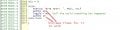
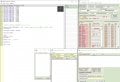
Ok, here's a screen grab of my hardware monitor with the code running as a test. It does send the text ok. Note that the TXbuf and TXshift Reg have the next 2 characters, once the first 2 (t and e) are displayed.
It does display faster than 9600baud, since the SIM just runs through the hardware UART code without waiting for baudrate generator. I find it puts a character out about every 40 to 50uS
The "te" shows up as soon as I step to the waitms 20
Hi,
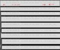
Here are some Digital analyser readings, from between the UART and the radio. I'm trying to figure them out.
The program LOOP has 0-20 output, but the Terminal shows every odd reading, as above.
To me, there doesn't seem enough room for a BYTE?
C
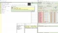
Only settings are what you see in the program. I notice in your screen shot that you have the software UART monitor open, listening to pin 7 of PortC, which is a hardware UART pin. That may be messing up your test results. Do not use software UART monitor when using the hardware UART monitor in the SIM. That is, don't use both at the same time unless the soiftware UART is on different pins than the hardware UART
Only settings are what you see in the program. I notice in your screen shot that you have the software UART monitor open, listening to pin 7 of PortC, which is a hardware UART pin. That may be messing up your test results. Do not use software UART monitor when using the hardware UART monitor in the SIM. That is, don't use both at the same time unless the soiftware UART is on different pins than the hardware UART
Hi S,
I'm trying tests for hour on end, When I'm trying SIM, I have the SW UART or HW UART, and perhaps leave it on screen while I test the HSEROUT 'live', but I don't try both at the same time.
I use PIN 44 RC6 of the 18F46K20 for HSEROUT 'live' or for SEROUT tests, as this is the connection to the radio on the PCB.
At the moment there is no receive while testing the HSEROUT, but when used in the full program, it goes through a switch along with other inputs. (This will change soon, so leave for now)
 Facebook
 Google
 GitHub
 Linkedin
") )
)