Facebook
 Google
 GitHub
 Linkedin
Hi,
I'm puzzled!
I'm trying to READ the Altimeter measurement data for the registers. The D/S suggests BURST READ.
I've tried individually, and it appears that there is nothing in the registers, note: 2x of them are 0x80, which I can see.
If they are being READ as a series, how do I READ them? Is SSPBUF still involved?
C
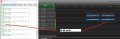
Attachments
-
 176.3 KB Views: 4