Facebook
 Google
 GitHub
 Linkedin
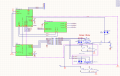
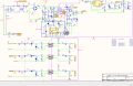
I have relay delay circuit as follow:

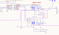
Relay for Channel A and Relay for Channel B

My question is that why zero cross delay varies at channel B while channel A is constant whenever I measure it. While I stop a while and go back to measure channel B, the zero cross delay varies. Firmware also controls its output too.
Please help why the zero cross delay in channel B are not stable, that in channel A stable.
Thanks
Relay for Channel A and Relay for Channel B
My question is that why zero cross delay varies at channel B while channel A is constant whenever I measure it. While I stop a while and go back to measure channel B, the zero cross delay varies. Firmware also controls its output too.
Please help why the zero cross delay in channel B are not stable, that in channel A stable.
Thanks
Attachments
-
 54 KB Views: 1