Yeah, this could work. But there's still the issue when there's no 400V there's no indication of relay position. And the issue of using a regular toggle switch - I don't have a drawing of one with a center off spring load. We'll have to use some imagination.
Do we know for sure the resistance and voltage rating for the relay coils?
(Needed to calculate R and C values for post #45 circuit)
The resistor in series with the neon should 1.8MΩ and must be rated for 400VAC which probably means at least two resistors in series to get the voltage rating.
OK, a 12V DC coil with a resistance of 144Ω (both set and reset) with a rated current of 83.3mA; Thanks for making me take another look at that. With the drawing in post #45 we should be able to determine the resistors and capacitors for this to work. Keep in mind you will have to discern the position of the switch in order to determine the likely position of the relay, whether it's open or closed.
But why are you doing this? You say you're not using the relay for active switching, so why is it there? You're not going to turn something on or off - so I'm wondering why this unnecessary step. I'm sure you have something in mind, like maybe a lock-out - or maybe an indicator of whether it's locked out or not. But if that's the case then whomever is performing maintenance on the machine should shut the breaker off and unplug the equipment - and put a "Lock-Out - Tag-Out" device on it to prevent someone from accidentally energizing the machine. The breaker should be locked off. The plug should be inclosed in a locked case to prevent someone from plugging it into another power source.
Sorry - but I keep going back to that safety thing.
View attachment 227900
OK, a 12V DC coil with a resistance of 144Ω (both set and reset) with a rated current of 83.3mA; Thanks for making me take another look at that. With the drawing in post #45 we should be able to determine the resistors and capacitors for this to work. Keep in mind you will have to discern the position of the switch in order to determine the likely position of the relay, whether it's open or closed.
But why are you doing this? You say you're not using the relay for active switching, so why is it there? You're not going to turn something on or off - so I'm wondering why this unnecessary step. I'm sure you have something in mind, like maybe a lock-out - or maybe an indicator of whether it's locked out or not. But if that's the case then whomever is performing maintenance on the machine should shut the breaker off and unplug the equipment - and put a "Lock-Out - Tag-Out" device on it to prevent someone from accidentally energizing the machine. The breaker should be locked off. The plug should be inclosed in a locked case to prevent someone from plugging it into another power source.
Sorry - but I keep going back to that safety thing.
Do you not see the dual coil in the drawing? A set coil on top and a reset coil on the bottom. OK maybe not conventionally drawn, but nevertheless, there's two coils in my drawing. Maybe I should delete the C and the NO. Sorry for the confusion.
Do you not see the dual coil in the drawing? A set coil on top and a reset coil on the bottom. OK maybe not conventionally drawn, but nevertheless, there's two coils in my drawing. View attachment 227907
Hey Guys, Thank you so much for lot of inputs. After going through all the solutions (Some answers I could not understand) I think there are 2 possible solutions, one is to use normal toggle SPDT switch with capacitors post #45 and another one is to use neon indicator across the output of the relay. I am afraid the wiring is wrong in post #45 since the common connection is positive. And also I am having the relay with 5V DC coil.
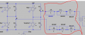
Breif intro :-The relay is being used to short the inductor path, if the relay is turned on, the 400AC from the tap of the inverter will take the path through the relay, when it is off it takes the path of inductor. I could have used SPDT relay to manipulate the flow between two lines but i could not find the relay rated for 40A and 400V rms. So I am using SPST relay.
As I said i will not do live switching. Once I energize the coil and the contacts are made then I power up the circuit and before I reset the relay coil, I turn of the whole circuit and then reset it ( Because it is not recommended to do live switching at this power rating). I hope now you get some feeling of what I am doing.
Now, I feel the 2 solutions i mentioned would do the job. Could you please tell me how to calculate the capcitor value for the 5V coil and also about neon indicator wiring.
I also thought about the digital latching or flipflop but I have poor knowledge in digital electronics.
Also, I was thinking considering momentary SPDT, what if I simply set or reset the relay irrespective of the previous position? ex: I just set the contacts of the relay which is already in the set position. Does it affect the relay coil? Just a thought
I really appreciate your answers. Thank you guys
Hey E, I think I have to ground the other end of Neon since I am working in the primary side of the resonant converter. As i said 400V are coming from the taps of the inverter. I attach the picture for reference.
I also have confusion in wiring of the relay coil. we have three terminals one is common positive and another two is negative terminal (Ground) for set and reset. I just have to connect 5V directly to positive terminal and connect two negative set/reset terminal to two outer pins of the SPDT switch and center pin being ground/negative terminal right? Please let me know if I am correct.
hi E,
Got it. Thanks! Please let me know about the neon common terminal. Should the other end be connected to the ground considering my schematic? How big is gonna be the resistor.
I appriciate your support! Thank you
 Facebook
 Google
 GitHub
 Linkedin