hi,
Post a marked up drawing showing how the relay contacts will be used, also the common 0V point for the 440V.
From that I could add the neon circuit.
REDRAW:
With a momentary switch you don't need capacitors. With a toggle you do. The caps will energize the coil momentarily but when they charge they will stop conducting. The 1 MEG Ω resistors are to drain the caps of their charge. They're that high so they don't draw much current. At 5V with a 1 MEG resistor, the current draw will be 0.000005A (5 µA [not 5mA]). If running on batteries, with a toggle you have a constant draw of current. With the momentary switches you don't have that concern. The 470µF caps will give you a long enough pulse to latch the relay. As for exact timing - that's not necessary; just as long as the pulse is long enough to fully engage the relay and you're good.
With the toggle you have a visual indication of the contact position. With the momentary you don't. For an indicator you'll need more circuitry than just whether the NEON lamp is lit or not. I'd opt for a toggle or even a slide switch. The slide switch will be smaller. And with a DPDT slider you can use the extra contacts to indicate position with a lamp or LED.
[edit] and we don't know if the 400 is AC or DC. I'm assuming AC. Please clarify. And as for the 1 meg resistors, you can also use a lower value. If you're going to be switching this back and forth frequently then a lower resistance will work better.
REDRAW: View attachment 227958
With a momentary switch you don't need capacitors. With a toggle you do. The caps will energize the coil momentarily but when they charge they will stop conducting. The 1 MEG Ω resistors are to drain the caps of their charge. They're that high so they don't draw much current. At 5V with a 1 MEG resistor, the current draw will be 0.000005A (5 µA [not 5mA]). If running on batteries, with a toggle you have a constant draw of current. With the momentary switches you don't have that concern. The 470µF caps will give you a long enough pulse to latch the relay. As for exact timing - that's not necessary; just as long as the pulse is long enough to fully engage the relay and you're good.
With the toggle you have a visual indication of the contact position. With the momentary you don't. For an indicator you'll need more circuitry than just whether the NEON lamp is lit or not. I'd opt for a toggle or even a slide switch. The slide switch will be smaller. And with a DPDT slider you can use the extra contacts to indicate position with a lamp or LED.
[edit] and we don't know if the 400 is AC or DC. I'm assuming AC. Please clarify. And as for the 1 meg resistors, you can also use a lower value. If you're going to be switching this back and forth frequently then a lower resistance will work better.
Hey Tony,
The line will be 400V AC.
could you please tell me how did u calculate the capacitor value?
If i use the normal toggle switch with caps, then the supply will be going to the coil always right? in this case, it might damage the coil of the relay right? I guess min of 100ms and max of few seconds of supply would be enough...? or I did not understand the logic may be.
First, I used caps that worked for me with my relays. I've done something similar. Using large enough caps will draw sufficient current to close the contacts (or open them). There's a formula for calculating RC circuits, which is what your coil and cap form. The extra resistor is to drain the cap of charge when it's de-energized. Also, the large resistance is to prevent the power source from having to supply too much current - AND to prevent drawing too much current through the relay coil. Whether the relay is energized for 100mS or for 2000mS (2 seconds), at 5V there won't be much heating. I'll look back at the specs because I thought you were describing using a 12 volt relay. But I didn't calculate anything.
I just grabbed a 12VDC relay and a 470µF (25V) cap and bench tested it. The period of time the relay clicks and holds is just a guestimate, but it seems like it's clicking in for a quarter of a second. I suspect with 5V it will be at least twice as long, but shouldn't exceed one second. Each time I de-energize the cap I have to short the leads so that I can perform another test. That's what the resistor is for - to de-energize the cap.
OK, 5V supply with a coil resistance of 25Ω, you're going to push 200mA through the coil. At 200mA and 5V, that's going to be 1 watt. I don't think you're going to have to worry about harming the coils. If I can come up with a 5V relay I'll experiment with that and capacitors and let you know what I observe. Sometimes in electronics, the best way to determine a value is to test and adjust till you get what you want.
OK, 5V supply with a coil resistance of 25Ω, you're going to push 200mA through the coil. At 200mA and 5V, that's going to be 1 watt. I don't think you're going to have to worry about harming the coils. If I can come up with a 5V relay I'll experiment with that and capacitors and let you know what I observe. Sometimes in electronics, the best way to determine a value is to test and adjust till you get what you want.
Thank you for the clear answer.
I believe u looked the parameters of 1 coil latching. I am using dual-coil latching, 1W, 12.5 ohm and 400mA. Would the cap values remain same with dual-coil latching parameters?
Also, I just want to make sure relay coil stay safe or doesnt get too heated up and burn.
I appreciate your help. Thank you
I used a toggle switch (SPDT) to indicate position. And a momentary switch in series with the common to activate. While not foolproof, as long as the operator was careful, it worked for my application.
I used a toggle switch (SPDT) to indicate position. And a momentary switch in series with the common to activate. While not foolproof, as long as the operator was careful, it worked for my application.
Another good way to do this!
But the little catch is that we have to remember to activate the common after SET/RESET. Since I am operating with many relays like this.
For an instance lets say, I activate the relay by keeping the toggle switch in SET position after some time I activate the relay again keeping the toggle position in SET position, In this case, will the coil burn? or does it cause any problem if i give the pulse again?
Please let me know. And also for the case with RESET position.
You could use a series of relays all with toggles wired to a common ground. The common ground can have a single push button so that when you set all your relays then push just the one button, all relays are set to that setting. I'll bang out another picture.
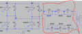
If you want to try using a flip flop, here's one way. It's more involved though than using a toggle switch and passive circuit.
The button is an ordinary momentary NO push button. R3/R6 set the pulse duration.
You can add LED indicators in parallel with each coil to indicated status (as long as it doesn't need to be fail safe).
The CD4013 comes with two FF in a package, so I used one to square up the PB input signal.
You could use a series of relays all with toggles wired to a common ground. The common ground can have a single push button so that when you set all your relays then push just the one button, all relays are set to that setting. I'll bang out another picture.
The thing is I cannot set and reset all the relays at once because I need to set/reset when it is needed. U can check the positions of the relay in the attachment.
Thank you for the clear answer.
I believe u looked the parameters of 1 coil latching. I am using dual-coil latching, 1W, 12.5 ohm and 400mA. Would the cap values remain same with dual-coil latching parameters?
Also, I just want to make sure relay coil stay safe or doesnt get too heated up and burn.
I appreciate your help. Thank you
OK, yes, I see my mistake with the data sheet. 5V ÷ 12.5Ω = 40mA. 5V x .04A = 200mW. The lower resistance will mean the caps will charge faster. You may have to experiment to get a decent timing with the caps. I'm also sure someone here can probably give you a definitive answer based on calculations, but the math has always been a weak spot for me. I DO know some of the math, just not sure about how to answer the question regarding the size of the caps. But with a push button - again, you avoid the need for caps.
In the TS's drawing there are six relays, each drawing 40mA. [edit] 200mA [end edit] each. Six relays set at the same time would draw 240mA. [edit] 1.2A. [end edit] A single PB should be able to handle that current.
By way of argument - you've stated that no relay will be involved in "Live Switching". OK. That tells me that you're going to apply power and get an expected result depending on which relays are active. Assume you have relays A through F. You want A and B on while C through F are off. Set the toggles to those positions, then press the button. Watch for a drawing shortly.
If you want to try using a flip flop, here's one way. It's more involved though than using a toggle switch and passive circuit.
The button is an ordinary momentary NO push button. R3/R6 set the pulse duration.
You can add LED indicators in parallel with each coil to indicated status (as long as it doesn't need to be fail safe).
The CD4013 comes with two FF in a package, so I used one to square up the PB input signal.
In the TS's drawing there are six relays, each drawing 40mA. Six relays set at the same time would draw 240mA. A single PB should be able to handle that current.
By way of argument - you've stated that no relay will be involved in "Live Switching". OK. That tells me that you're going to apply power and get an expected result depending on which relays are active. Assume you have relays A through F. You want A and B on while C through F are off. Set the toggles to those positions, then press the button. Watch for a drawing shortly.
I have to keep changing the state of relay. Sometimes A, C, D or any random relay are used and sometimes not. Sometimes i only need to set the Relay A. Sometimes not at all
I have to keep changing the state of relay. Sometimes A, C, D or any random relay are used and sometimes not. Sometimes i only need to set the Relay A. Sometimes not at all
I have to keep changing the state of relay. Sometimes A, C, D or any random relay are used and sometimes not. Sometimes i only need to set the Relay A. Sometimes not at all
 Facebook
 Google
 GitHub
 Linkedin