Refining Square Sound Waves - RC Circuit / 555 timer

Thread Starter

alexkymberly

Joined Oct 17, 2016
7
Hi everyone!
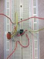
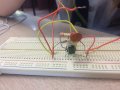
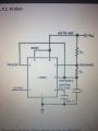
I am a student (only year 11) currently studying Electronically Generated Sound and my class is building RC circuits with 555 timers to reach a desired frequency of 440 Hz. Currently, my circuit look like pictures attached. The duty cycle is 50% according to oscilloscope and the frequency is almost exact. However, the sound waves are square, as I understand they always are in Astable circuits. For extra credit we have to refine the square waves into more sine-like shape. Does anyone know what I have to add or subtract in my circuit in order to achieve this? Also, anyone can define a duty cycle is and state the importance of it in an RC circuit it would be greatly appreciated. Thank you in advance!
 

Attachments

DickCappels

Joined Aug 21, 2008
10,661
The difference between a sine wave at 440 Hz and a square wave at 440 Hz is that the sine wave is (ideally) only contains 440 Hz. The square wave has not only 440 Hz but also odd harmonics.

Does that information bring any particular solution to mind?
 

ci139

Joined Jul 11, 2016
1,977
the following is not a response to the poster but a critics to kind of question setup (and someone standing on my nerves here - totally irrelevant)
so
how to slope the comparator output ???
► the first and easy way is to rise the frequency to reach the proportion (resembling to sine wave)
►► the second and not so easy way is to manipulate your threshold and retrigger levels dynamically -- basically build a driver to mod 555 into something it is not (it's even possible to achieve a close match to a sine that way)

by combining/modding elements from :
http://electronicscct.blogspot.com.ee/2011/11/555-timer-oscillator.html
more http://www.birthofasynth.com/Thomas_Henry/Pages/X-4046.html
it may be possible to convert the chip (555) into an Op Amp . . . http://www.learningaboutelectronics.com/Articles/Triangle-wave-generator-circuit-with-an-LM741-op-amp.php

555-Sine.png (something in between all of the above - not too universal - if it's not entirely yet another Spice illusion!) . . . mod for newer v. of spice R2 < 200k - set less than
-- the iC can be likely converted something chopped Op Amp , but yes thanks -- i'm not gonna try this . . .
 

Attachments

Last edited:

Thread Starter

alexkymberly

Joined Oct 17, 2016
7
The difference between a sine wave at 440 Hz and a square wave at 440 Hz is that the sine wave is (ideally) only contains 440 Hz. The square wave has not only 440 Hz but also odd harmonics.

Does that information bring any particular solution to mind?
Hi Mr Cappels, thanks for taking the time to reply to my question. I somewhat understand what you are saying, however I am new to physics class this term and I don't think I'm as up to speed as the rest. Could you help me further?
 

Thread Starter

alexkymberly

Joined Oct 17, 2016
7
the following is not a response to the poster but a critics to kind of question setup (and someone standing on my nerves here - totally irrelevant)
so
how to slope the comparator output ???
► the first and easy way is to rise the frequency to reach the proportion (resembling to sine wave)
►► the second and not so easy way is to manipulate your threshold and retrigger levels dynamically -- basically build a driver to mod 555 into something it is not (it's even possible to achieve a close match to a sine that way)

by combining/modding elements from :
http://electronicscct.blogspot.com.ee/2011/11/555-timer-oscillator.html
more http://www.birthofasynth.com/Thomas_Henry/Pages/X-4046.html
it may be possible to convert the chip (555) into an Op Amp . . . http://www.learningaboutelectronics.com/Articles/Triangle-wave-generator-circuit-with-an-LM741-op-amp.php
Thanks a lot for the help! I read somewhere that if i change the duty cycle it should make my wave more sine-like. do you know anything about that?
 

Kermit2

Joined Feb 5, 2010
4,162
Power transformers respond very poorly to freq in the upper range of human speech and get worse the higher the freq goes.

Feed a 555 timer square wave into a small 120 to 12 volt power transformer and look at the result. It should look much "rounder" than the signal you put in.

Just an old school hack to apply low pass filtering to audio range square wave oscillators. Stair step or "modified Sq wave" with a zero dc dead time between bipolar Sq wave pulses makes even better sine waves when filtered through a power transformer.

You will want a transistor buffer that can source at least 1 amp or so to drive the transformer filter. It's passive so you have to add power.
 

atferrari

Joined Jan 6, 2004
5,007
I think this will make it all clear. Use a low pass filter to reduce the odd harmonics that make the waveform square.

http://www.learningaboutelectronics.com/Articles/Square-to-sine-wave-converter-circuit.php
Definitely the simplest approach to get a clean (within reason) signal. It is also good for experimenting since you will be dealing with few, easy to get components.

Just in case, get used to match resistors / capacitors. It is even fun as long you are an organized experimenter.

I also went the step wave generation way but this time using a microprocessor. The filtering side consisted basically of the same. When I wanted it complicated I used a switched caps filter. A long fruitful way.
 

crutschow

Joined Mar 14, 2008
38,430
You could check what happens if you run the square-wave through an op amp integrator, and then run that output through another integrator (both with appropriate time-constants).
(The output is very close to a pure sinewave.)

The problem is that pure integrators will have a DC offset so you have to take care of that by appropriate AC coupling and some resistive feedback across the integration capacitor.
 
Top