Facebook
 Google
 GitHub
 Linkedin
I have asked this learned group many things and it great how you all help those of us learning…
That said I built a simple AM radio circuit just for fun. I know nothing about radios. I read it was simple and worked well. So I’ve built many things and love building circuits and was looking for a different direction.
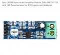
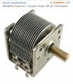
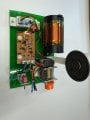
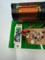
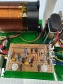
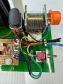
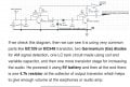
This circuit was a google search, seemed straightforward. I built it exactly but I get nothing—-nothing. I used an 8 ohm speaker and a simple 386 amp board I found online. Not a peep. My tank circuit is the 300uH air coil inductor and the variable tuning capacitor is the range specified. I have gone through the circuit and there are no errors. Please look at it and if possible offer me some direction to go…
That said I built a simple AM radio circuit just for fun. I know nothing about radios. I read it was simple and worked well. So I’ve built many things and love building circuits and was looking for a different direction.
This circuit was a google search, seemed straightforward. I built it exactly but I get nothing—-nothing. I used an 8 ohm speaker and a simple 386 amp board I found online. Not a peep. My tank circuit is the 300uH air coil inductor and the variable tuning capacitor is the range specified. I have gone through the circuit and there are no errors. Please look at it and if possible offer me some direction to go…
Attachments
-
 752.4 KB Views: 48