Questions about charge sensitive preamplifier

Thread Starter

bstdms

Joined Jun 14, 2023
22
1737206391165.png
1737206414623.png

Hello,
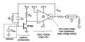
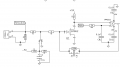
I am currently studying charge-sensitive preamplifiers. I found those two circuits from two papers, and I have several questions:
1. How does the positive feedback work? As I see in most tutorials, the feedback network is connected back to the inverting pin.
2. How is the JFET biased? I think it is working in saturation mode. Is VDS set through the opamp? Is VGS queal to 0V?

I appreciate your help.
 

Attachments

AnalogKid

Joined Aug 1, 2013
12,043
In both circuits, the FET is a signal inverter. Having that inside the feedback loop effectively flips the opamp's two inputs. From sensor input to opamp output (the two ends of the feedback components), the entire signal chain is inverting. Thus, the feedback is negative. This is a common situation in various forms of compound amplifiers.

ak
 

Thread Starter

bstdms

Joined Jun 14, 2023
22
In both circuits, the FET is a signal inverter. Having that inside the feedback loop effectively flips the opamp's two inputs. From sensor input to opamp output (the two ends of the feedback components), the entire signal chain is inverting. Thus, the feedback is negative. This is a common situation in various forms of compound amplifiers.

ak
Thank you I understand. Does the virtual short and virtual open still hold for the opamp in this situation?
 

Thread Starter

bstdms

Joined Jun 14, 2023
22
I built the same circuit as the first diagram. Vbb is set to be 1.6V, the JFET used is 2SK212D, and the opamp is AD8599.
I checked that the voltage at the inverting pin is Vbb, 1.6V.
Without connecting to input, the voltage at the JFET drain is always 0.6V, which is not correct as it should be the same as Vbb.

Any idea of the reason?
Thank you.
 

Thread Starter

bstdms

Joined Jun 14, 2023
22
Hi bst,
Compare the Gain curves for the BF862 versus the 2SK2 a factor 10 difference.
E
View attachment 340722
Thank you very much. Actually I’m confused about the FET here. In the two circuits they are working in saturation region thus Ids should be equal to Idd. But Vds and Rd also set the Ids in another way. Aren't those two values mutually exclusive?
 

Thread Starter

bstdms

Joined Jun 14, 2023
22
Thank you very much. Actually I’m confused about the FET here. In the two circuits they are working in saturation region thus Ids should be equal to Idd. But Vds and Rd also set the Ids in another way. Aren't those two values mutually exclusive?
Sorry I checked again that the JFET is working in linear region. And my circuit is working properly now.
 
Top