Questions about a circuit for staircase lights

Thread Starter

Inglorious89

Joined Feb 12, 2016
22
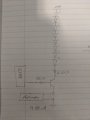
I'm designing a fairly simple circuit to provide LED lighting for my home's staircase whenever a motion sensor is tripped.

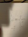
The motion sensor part of the circuit I have a good handle on (I'm using a 16F88 to accept the signal from the sensors, then to turn on the LED strips in kind), the LED side of the circuit is what I'm curious on. And on the schematic to clarify what the "x8" means, I'll have 8 LEDs in series for each strip, with a total of ~10 strips. Each strip would get its own 2N4401 for LED activation.

The schematic is attached. A few questions I have on it:
Is it going to be reliable long-term, or will I have an issue with LEDs burning out after a short while?
Is it viable for me to replace the resistor for the LED brightness with a rheostat to adjust their brightness on the fly, or is there a better way of being able to do so?
The capacitor is to provide a dimming effect when the LEDs lose power. Is this going to be safe/viable for a dimming effect, or is there a different way to provide a dimming effect that would be more efficient?
 

Attachments

dl324

Joined Mar 30, 2015
18,344
You're attempting to drive the LEDs high side with an NPN transistor. That's not going to work in your case; the LEDs will never turn on because the output from the PIC won't be high enough. You need to drive them low side.

A rheostat could be used to dim the LEDs, but you'd need one for each string. If you wanted all strings to be the same brightness, you could consider making the 24V supply variable. A better way to implement brightness control is to use PWM.

You have the capacitor connected backwards.
 

Thread Starter

Inglorious89

Joined Feb 12, 2016
22
You're attempting to drive the LEDs high side with an NPN transistor. That's not going to work in your case; the LEDs will never turn on because the output from the PIC won't be high enough. You need to drive them low side.

A rheostat could be used to dim the LEDs, but you'd need one for each string. If you wanted all strings to be the same brightness, you could consider making the 24V supply variable. A better way to implement brightness control is to use PWM.

You have the capacitor connected backwards.
By "high side" and "low side" I assume you mean the collector and emitter sides of the transistor?

I'll look into adding PWM functionality to the circuit, thanks for the suggestion.

As for the capacitor, I drew that part in a hurry before I took the picture. Probably should've double checked beforehand.
I'm assuming in theory it will work to dim the LEDs when the transistor is no longer saturated?
 

dl324

Joined Mar 30, 2015
18,344
By "high side" and "low side" I assume you mean the collector and emitter sides of the transistor?
Driving low side with an NPN transistor means switching the ground connection.
I'm assuming in theory it will work to dim the LEDs when the transistor is no longer saturated?
No. It will discharge when power is removed. You'll only get a dimming/fading effect if one or mote strings of LEDS are on when power is removed. Whether that effect will be significant depends on LED current being drawn at that time.
 

Thread Starter

Inglorious89

Joined Feb 12, 2016
22
Driving low side with an NPN transistor means switching the ground connection.
No. It will discharge when power is removed. You'll only get a dimming/fading effect if one or mote strings of LEDS are on when power is removed. Whether that effect will be significant depends on LED current being drawn at that time.
I'm running into a small problem when the transistor. I have everything wired as per the attached schematic, but whenever I apply 5VDC, ground, or even when I touch the 450 ohm resistor, the LEDs light up. Not at full brightness, but they do light up.

I imagine the transistor is being forward biased to some degree, but I'm not sure how to prevent that until there's 5VDC on that resistor.

Thanks for the help so far, by the way
 

Attachments

djsfantasi

Joined Apr 11, 2010
9,237
What voltage are you running the 16F88 at? I’m going to assume 5V for a minute.

You need 1.6A to illuminate 8 LEDs in parallel. I’m making some typical assumptions here. 20mA per LED, for example. Hence, you need 0.16A or 160mA on the base of the transistor At 5V, A 27Ω resistor is what’s needed to drop 160mA across 4.3V (accounting for the Vbe voltage drop).

You’ve got a 450Ω resistor there... This give you 10mA on the base. Much lower than 160mA. Maybe it’s enough to light the LEDs, but external influences can light them as well...

Try a 27Ω resistor...
 

Thread Starter

Inglorious89

Joined Feb 12, 2016
22
hi Ing,
Change the 10K to 2k2 resistors, the 10k is much to high a value.
E
Aaaand that did it, thanks!
Mind if I ask you what change that made so I can understand why the 10k was too high, but a 2k (or a 2.2k in this case, I didn't have a 2k resistor handy) works correctly?
 

Thread Starter

Inglorious89

Joined Feb 12, 2016
22
What voltage are you running the 16F88 at? I’m going to assume 5V for a minute.

You need 1.6A to illuminate 8 LEDs in parallel. I’m making some typical assumptions here. 20mA per LED, for example. Hence, you need 0.16A or 160mA on the base of the transistor At 5V, A 27Ω resistor is what’s needed to drop 160mA across 4.3V (accounting for the Vbe voltage drop).

You’ve got a 450Ω resistor there... This give you 10mA on the base. Much lower than 160mA. Maybe it’s enough to light the LEDs, but external influences can light them as well...

Try a 27Ω resistor...
To clarify, the LEDs are connected in series, not parallel. I drew out the full schematic to better clear up everything.
When the LEDs are lit, their draw is 13.58mA according to my meter.
 

Attachments

djsfantasi

Joined Apr 11, 2010
9,237
To clarify, the LEDs are connected in series, not parallel. I drew out the full schematic to better clear up everything.
When the LEDs are lit, their draw is 13.58mA according to my meter.
I was misled by another post. My fault. So if they draw 13.58mA, then the base current should be 1.358mA. At 5V less a Vbe of 0.7V, you’ll need a 320Ω base resistor to get close to 13.58mA. A 450Ω base resistor gives you 9.5mA for the LEDs. Probably enough to light them, but a narrow range that could result in inadvertent lighting.

Please clarify another thing. What are the LEDs Vf and maximum current draw. I’m assuming a Vf of 2.0V and maximum current of 20mA
 

Thread Starter

Inglorious89

Joined Feb 12, 2016
22
I was misled by another post. My fault. So if they draw 13.58mA, then the base current should be 1.358mA. At 5V less a Vbe of 0.7V, you’ll need a 320Ω base resistor to get close to 13.58mA. A 450Ω base resistor gives you 9.5mA for the LEDs. Probably enough to light them, but a narrow range that could result in inadvertent lighting.

Please clarify another thing. What are the LEDs Vf and maximum current draw. I’m assuming a Vf of 2.0V and maximum current of 20mA
Max current draw is 30mA and the typical Vf is 3.2V.
Here's the datasheet if you're curious: https://www.cree.com/led-components/media/documents/C513A-WSN-WSS-MSN-MSS-1042.pdf
 

djsfantasi

Joined Apr 11, 2010
9,237
Max current draw is 30mA and the typical Vf is 3.2V.
Here's the datasheet if you're curious: https://www.cree.com/led-components/media/documents/C513A-WSN-WSS-MSN-MSS-1042.pdf
Thanks for the datasheet. I didn’t look at it because I immediately saw a problem. Eight LEDs with Vf of 3.2V needs 25.6V to illuminate, plus some overhead for the current limiting resistor 8 * 3.2 = 25.6V. Plus 2V (random selection) overhead... 27.6V required; 24V available. See a problem?

You have 24V, which is not enough to light eight LEDs in series.

Due to variations in LED specs, you might be lucky enough to light them. But you can’t guarantee there’ll be no problems as there isn’t enough headroom for the current limiting resistor.

20mA * 8 = 160mA = 0.160A
Damn decimal point.
 

bertus

Joined Apr 5, 2008
22,931
Hello,

You say you have a powersupply of 24 Volts.
What kind of leds are you using?
White leds will have a voltage drop of 3 to 3.5 volts each.
8 of those leds in series will not light.

Bertus
 

ericgibbs

Joined Jan 29, 2010
21,452
Last edited:

Thread Starter

Inglorious89

Joined Feb 12, 2016
22
hi,
I think we have two different project from two different posters.???
One is showing a parallel LED connection and the other a series LED connection.

Will the original thread starter @Inglorious89 please confirm the connection and the other poster @iimagine please start his own thread....:rolleyes:

Eric
@bertus


Mod Note: created a new thread for @iimagine
https://forum.allaboutcircuits.com/threads/led-circuit-for-staircase-lights.162062/
To clarify my circuit:
The first schematic in the OP shows the "x8" next to the single LED, what I meant by this was that there will be 8 LEDs connect in series, not parallel.I should've drawn out the full circuit to avoid confusion, but I was being lazy.

The LEDs were intended to be connected in series, and currently are connected that way. I'll make sure to specify this in the schematic next time.
 

ericgibbs

Joined Jan 29, 2010
21,452
hi 89,
As @bertus points out,post #13, 8 LED's in series that have a nominal 3Vfwd operating voltage may not work as expected from a 24Vdc supply.
Are they White LED's.
E
 

Thread Starter

Inglorious89

Joined Feb 12, 2016
22
Hello,

You say you have a powersupply of 24 Volts.
What kind of leds are you using?
White leds will have a voltage drop of 3 to 3.5 volts each.
8 of those leds in series will not light.

Bertus
In my defense, I checked the voltage drop across each LED and they're dropping ~2.5V - 2.7V. I used a similar circuit for a previous project and from what I recall (the project was ~2 years ago, and like an idiot I didn't take good notes as to how I built the thing) the LEDs were able to run reliably.

Also, to clarify, I have the LEDs on a breadboard right now and they are lighting fairly well. Whether or not they're going to light reliably is another question, I realize. No matter what I'm going to be running stress tests on them, and if they start failing I'll take a few out of the circuit.
 

djsfantasi

Joined Apr 11, 2010
9,237
To clarify my circuit:
The first schematic in the OP shows the "x8" next to the single LED, what I meant by this was that there will be 8 LEDs connect in series, not parallel.I should've drawn out the full circuit to avoid confusion, but I was being lazy.

The LEDs were intended to be connected in series, and currently are connected that way. I'll make sure to specify this in the schematic next time.

And as Bertus stated in post #13, if those LEDs are connected in series, they will not and cannot light!

You’ll need a series/parallel circuit. Connect four LEDs in a series strung with the appropriate current limiting resistor. Then connect two such strings in parallel to get eight LEDs that will light.

UPDATE: the preceding posts from ericgibbs and the TS were posted while I was typing. At a Vf of 2.7V, the circuit is possible.
 
Top