Having questions about an Impulse Detector Circuit for My Geiger Counter

Thread Starter

DragonSlayer1355

Joined Jun 23, 2024
4
Hello everyone,

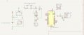
Recently, I've been working on building a Geiger counter using a guide. I've assembled everything, and it all seems to be functioning correctly: the tube is working properly, the high voltage generator is operating, and the display is on. However, I'm not seeing an increase in counts per second (cps) on my display.

After testing with a multimeter, I found that the voltage on the D2 pin is around 0.5V. I'm considering using an operational amplifier, like an LM358P or LM324N, to amplify the impulses coming from the tube and then send them to the D2 pin to reach at least 3,6V.

What do you think I should do in this situation?

You can see the schematic below ( I've replaced R2 with 10M and R1 with 100k)

Thanks for your help!
 

Attachments

Thread Starter

DragonSlayer1355

Joined Jun 23, 2024
4
I cannot figure out heads or tails in your circuit diagram. Where did you find this circuit?


Hello, thank you for taking the time to reply.

This schematic is a modified version I made of a diagram I found online. The circuit consists of three modules:

  1. Charging Module: This module includes a Li-ion accumulator, a TP4056 module for recharging, a switch, and a boost converter that increases the voltage from 3.7V to 5V.
  2. High Voltage Module: This module consists of a high voltage generator connected to a Geiger tube, along with a circuit made from a transistor, capacitor, and resistor for filtering and amplification.
  3. Control Module: This module features an Arduino Nano, an OLED display, and a Bluetooth module.

Thank you again .xd
 

LesJones

Joined Jan 8, 2017
4,511
It looks to me that the emitter and collector are reversed in your circuit.
Do you have weak pullup enabled on input D2 on the Arduino ? This is because you do not have a pullup resistor on the transistor collector.
The current pulse from the GM tube to the base of the transistor will cause the transistor to conduct.
This will cause a negative pulse at the transistor collector.
Do you see a positive pulse of about 0.6 volts on the transistor base with your oscilloscope ?
Do you see a negative pulse of about going from + 3.3 or +5 volts to zero volts at the transistor collector with your oscilloscope ? (This is with the transistor connected with it's emitter connected to 0 volts. NOT the the way it is commevted in your circuit.)

Les.
 

Dave Lowther

Joined Sep 8, 2016
332
I'm considering using an operational amplifier, like an LM358P or LM324N, to amplify the impulses coming from the tube
I built one several years ago. I don't remember how I came up with the scheme to convert raw pulses output by the tube into something the microcontroller would see as a pulse. It works well. Sorry about the difficult to read schematic. I did it based on the physical layout of the connectors on the veroboard. Essentially an open collector output from the transistor to the internal pullup on the microcontroller input port.
1719220675357.png
1719220977843.png

[Edit] I found some notes in my log book. The pulse output by T1is about 300uS
1719221502812.png
 
Last edited:

MisterBill2

Joined Jan 23, 2018
27,193
I built one several years ago. I don't remember how I came up with the scheme to convert raw pulses output by the tube into something the microcontroller would see as a pulse. It works well. Sorry about the difficult to read schematic. I did it based on the physical layout of the connectors on the veroboard. Essentially an open collector output from the transistor to the internal pullup on the microcontroller input port.
View attachment 325314
View attachment 325316

[Edit] I found some notes in my log book. The pulse output by T1is about 300uS
View attachment 325317
The signal looks like it is shunted by the 220 pf capacitor. I SEE no pullup resistor on the collector of T1. and there is a 4.7 meg resistor in series with the signal path, but it should only be in series with the high voltage source.

That circuit drawing is tedious to follow, and you have effectively blocked the signal path. The signal from the GM tube should be capacitor coupled to the transistor base, instead it is capacitor bypassed and 4.7 megohm resistor attenuated.
 

Dave Lowther

Joined Sep 8, 2016
332
That circuit drawing is tedious to follow.
I know. That's why the text you quoted says "Sorry about the difficult to read schematic".

I SEE no pullup resistor on the collector of T1.
That's because it's inside the microcontroller. You quoted my text which contains "internal pullup on the microcontroller input port ".
As for your other points you may well be right. I did say that I couldn't remember how I came up with that scheme. I may have copied it from somewhere. I looked at a few geiger counter projects from magazine articles when I was working out how to make it. The only reason I posted it was to help the OP by showing a working version similar to the OP's non-working version.
[Edit] After looking through the folder where I kept my notes about researching published geiger counter projects, it looks like I used the impulse detector here
 
Last edited:
Top