Question on condenser microphones circuitery

Thread Starter

M4rtin

Joined Oct 15, 2026
4
Hiii, so I'll prefase this question by sating that I've just gotten started learning basic electronics for DIY microphones by myself, so bare with me if this is obvious. Basically, I wanted to better understand the difference between the most basic circuit possible (least amount of components) for both a microphone built with an electret capsule and one with a "true" condenser large diaphragm capsule.
I understand the difference between the two capsules, however: I found this schematic, which features only a 2n5457 FET, a 10kOhm resistor, and a coupling cap, wired as source follower if I'm not mistaken.
In one video I saw, the person seemed to be using an electret capsule (
). But in this other video, the same schematic appears in a design that seems to be using a true condenser (
).
How could this virtually be possible? In the last resource I found (https://audioimprov.com/AudioImprov/Mics/Entries/2021/2/5_Circuits_-_Simple_to_Professional.html ), the second circuit shown appears to be the same schematic as the previous 2, and it states it should work for an externally polarised capsule. However, the FET model is different.
What is the correlation between these and does anyone have any clue on how the schematic for a basic true condenser capsule could look like? Online I can mostly find premade designs implemented on a circuit board. Or if I would like to use a similar schematic as the one shown in the resources, should I use an electret capsule and call it a day or is there any way to tweak the circuit so that it could work for an externally polarised one?

Thank you so much in advance :))
 

MrChips

Joined Oct 2, 2009
35,299
There are basically two main types of microphones, (1) dynamic mics (2) condenser mics.
There are other types of microphones which we will ignore for this discussion.

Condenser mics and electret mics fall into the same category. They have high output impedances. A FET preamp is the most common circuit used for these types of mics.

The question you need to ask is, "Is the FET preamp already embedded in the microphone?". A preamp needs power. This is where "phantom power" comes in. Phantom power is the external power supply needed to power the microphone's internal preamp.

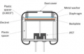
Electret mics have the FET built in. What it needs is a power source and an external load resistor. The output signal level is usually high enough for most applications. If you need to amplify the signal, you can add a single stage amplifier. It does not require a high impedance input.

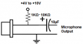
Here is an amplifier circuit that uses a single 2N3904 BJT stage.
R1 is the load to the mic that supplies the mic with power.

1792540183116.png
 

MisterBill2

Joined Jan 23, 2018
28,550
There are two realms of "condenser" microphones: Non-polarized and polarized!
the POLARIZED microphones have a charge premanently placed on the diaphram, and thus they do not need an external polarizing voltage source, and usually no blocking capacitorto the forst amplifier device.
The NON-POLARIZED capacitor microphones DO require an external higher voltage source, fed thru a high value series resistor, and a capacitor to couple the output signal voltage.
 

Thread Starter

M4rtin

Joined Oct 15, 2026
4
There are basically two main types of microphones, (1) dynamic mics (2) condenser mics.
There are other types of microphones which we will ignore for this discussion.

Condenser mics and electret mics fall into the same category. They have high output impedances. A FET preamp is the most common circuit used for these types of mics.

The question you need to ask is, "Is the FET preamp already embedded in the microphone?". A preamp needs power. This is where "phantom power" comes in. Phantom power is the external power supply needed to power the microphone's internal preamp.

Electret mics have the FET built in. What it needs is a power source and an external load resistor. The output signal level is usually high enough for most applications. If you need to amplify the signal, you can add a single stage amplifier. It does not require a high impedance input.

Here is an amplifier circuit that uses a single 2N3904 BJT stage.
R1 is the load to the mic that supplies the mic with power.

View attachment 372447


Thank you so much for your reply!

I understood this part of the conversation, hence why I was confused about the resources I attached which seemed to claim that the same circuit could've worked for both capsules. So basically if non polarised capsules don't have said FET preamp circuit imbedded in them I just have to build it myself?
Correct me if I'm wrong, but isn't the capsule being used in the schematic you attached polarised? Though it uses another transistor in its circuit, so I'm guessing then that you'd need more than just a power source and a resistor?
Because I believe I understand that circuit.

However, I couldn't quite grasp how to build the most basic circuit possible for microphones that used non polarised, so based on your answer I'd say I just need to recreate myself the FET imbedded in electret capsules? and then add another load resistor to supply the power?

Anyways thank you again for taking the time :)
 

Thread Starter

M4rtin

Joined Oct 15, 2026
4
There are two realms of "condenser" microphones: Non-polarized and polarized!
the POLARIZED microphones have a charge premanently placed on the diaphram, and thus they do not need an external polarizing voltage source, and usually no blocking capacitorto the forst amplifier device.
The NON-POLARIZED capacitor microphones DO require an external higher voltage source, fed thru a high value series resistor, and a capacitor to couple the output signal voltage.

Ok awesome so based on this answer, the second schematic of this article (https://audioimprov.com/AudioImprov/Mics/Entries/2021/2/5_Circuits_-_Simple_to_Professional.html ) should work for non polarised capsules? Because I thought this circuit wouldn't have been enough to feed the necessary polarising voltage.
This is what I wanted to establish, how can I the most basic a circuit to feed the polarising voltage to the true condenser capsule that electret ones don't need

Thank you so much for taking your time to reply :)
 

Thread Starter

M4rtin

Joined Oct 15, 2026
4
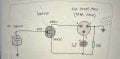
Better said, I just would like to understand if I could've used this schematic with an externally polarised capsule and call it a day, thanks for the patience ;)

IMG_5851_(1).jpg
 

MisterBill2

Joined Jan 23, 2018
28,550
I doubt thst the circuit in post #6 will work at all. I see no source of any bias for the gate of the 2N5457, nore any voltage for the externaly polarized capacitor microphone.
 

panic mode

Joined Oct 10, 2011
5,448
lets back up a little...

TS clearly stated that he understands the difference between polarized and non-polarized mics.
he also asked specifically how is that the youtube circuits are apparently the same in both cases when they need different bias/voltage.

yet most of the replies focus on electret (polarised) microphones, show various things like mention dynamic mics, vent holes in the electret capsule or how to interface electret mic but they completely ignore the asked question.

non-polarized capacitive mics are basically just a low value capacitor and need both high voltage and amplifier with very high impedance (FET). to polarize capacitor, there need to be biasing resistor of very high value (tens of GOhm). in some cases this resistor is omitted so bias is only through leakage current.

polarized capsule mics (electret) have charge permanently embedded into membrane and can operate with much lower voltage. also since they already have FET amplifier, they are low impedance (few kOhm) so that they can directly interface to just about anything - even BJT amp. they do need biasing resistor of medium value (few kOhm)

so the way i read his post, the question is what happens/does it really work if the two FET circuit stages are cascaded, one is inside electret mic and another one is external (with phantom power). since there is no obvious resistor on gate of external FET, if this works, it must be also because of leakage current.
 
Last edited:

MisterBill2

Joined Jan 23, 2018
28,550
lets back up a little...

TS clearly stated that he understands the difference between polarized and non-polarized mics.
he also asked specifically how is that the youtube circuits are apparently the same in both cases when they need different bias/voltage.

yet most of the replies focus on electret (polarised) microphones, show various things like mention dynamic mics, vent holes in the electret capsule or how to interface electret mic but they completely ignore the asked question.

non-polarized capacitive mics are basically just a low value capacitor and need both high voltage and amplifier with very high impedance (FET). to polarize capacitor, there need to be biasing resistor of very high value (tens of GOhm). in some cases this resistor is omitted so bias is only through leakage current.

polarized capsule mics (electret) have charge permanently embedded into membrane and can operate with much lower voltage. also since they already have FET amplifier, they are low impedance (few kOhm) so that they can directly interface to just about anything - even BJT amp. they do need biasing resistor of medium value (few kOhm)

so the way i read his post, the question is what happens/does it really work if the two FET circuit stages are cascaded, one is inside electret mic and another one is external (with phantom power). since there is no obvious resistor on gate of external FET, if this works, it must be also because of leakage current.
I addresed that, although not adequately, in post #7.
AND I never trust device leakage current to be the desired amount.
 
Top