PWM waxing and waning LEDs problem

Thread Starter

tracecom

Joined Apr 16, 2010
3,944
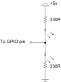
The purpose of the following code is to cause a red LED to go from dim to brite and back to dim in about two seconds. At the same time, a greed LED is supposed to go from bright to dim and back to bright. In other words, while one LED is getting brighter, the other is getting dimmer, and vice versa.

Amazingly, the code is working with one minor glitch: as each LED gets to its maximum brightness, it switches off for a tiny, but discernable amount of time. I guess it probably does the same thing as it gets to its minimum brightness, but I can't see that.

Is it an arithmetic problem in my for next loops?

Thanks for your input.

Rich (BB code):
' Name        : Aviation Nav Lights 1.pbp
' Compiler    : PICBASIC PRO Compiler 3.0
' Assembler   : MPASM
' Target PIC  : 8-pin PIC12F675 or similar types
' Hardware    : CRH Breadboard
' Oscillator  : 4MHz internal
' Description : 
Define  OSCCAL_1K  1        ' Calibrate internal oscillator
Green Var GPIO.1            ' Green LED pin
Red var GPIO.0              ' Red LED pin
highval Var byte            ' Create highval to store high start value
lowval var byte             ' Create lowval to store low start value
increment var byte          ' Create increment to store steps
   ANSEL = %00111111        ' Set all digital
   CMCON = 7                ' Analog comparators off
highval = 255
lowval = 0
mainloop:
    for increment = 1 to 128
    pwm green, highval, 1   ' PWMs Grn LED at highval for 1 cycle (about 5 ms.)
    pwm Red, lowval, 1      ' PWMs Red LED at lowval for 1 cycle (about 5 ms.)
    highval = highval - 2   ' Green LED is dimming; RED is brightening.
    lowval = lowval + 2
next increment
    for increment = 1 to 128
    pwm Red, highval, 1     ' PWMs Red LED at highval for 1 cycle (about 5 ms.)
    pwm Green, lowval, 1    ' PWMs Grn LED at lowval for 1 cycle (about 5 ms.)
    lowval = lowval + 2     ' Red LED is dimming; Green is brightening.
    highval = highval - 2
next increment
   Goto mainloop            ' Do it forever
   End
BTW, this is for an RC model aircraft, so Mods, don't be alarmed.
 
Last edited:

thatoneguy

Joined Feb 19, 2009
6,359
I'm a bit confused by "1 cycle" in the pwm command.

I think what is happening is between the fade in loops and fade out loop, there is a pause when the outputs are at zero rather than pwm.

Why not use a single byte variable for both, call it TheVal

Use TheVal to decide brightness of one LED, and 255-TheVal for the one "out of phase"

Once you attempt to add 2 to TheVal when it is 254, it will overflow and start again from 0.

If the value needs to be between 0 and 128, use TheVal/2 or TheVal>>1 or whatever BASIC likes prior to sending it to pwm command.

This will neaten up the code and eliminate any break between loops. I don't know exactly how the compiler works, but it could be worth a shot.

Rich (BB code):
' Compiler    : PICBASIC PRO Compiler 3.0 
' Assembler   : MPASM 
' Target PIC  : 8-pin PIC12F675 or similar types 
' Hardware    : CRH Breadboard ' Oscillator  : 4MHz internal 
' Description :  
Define  OSCCAL_1K  1        ' Calibrate internal oscillator 
Green Var  GPIO.1            ' Green LED pin 
Red var GPIO.0              ' Red LED pin 
TheVal Var byte             ' Byte to store PWM Level    
ANSEL = %00111111        ' Set all digital    
CMCON = 7                ' Analog comparators off theval=0 
mainloop:     
     pwm Green, 255-TheVal, 1    ' PWMs Grn LED at highval for 1 cycle (about 5 ms.)     
     pwm Red, TheVal, 1  ' PWMs Red LED at lowval for 1 cycle (about 5 ms.)     
     TheVal = TheVal + 2    
Goto mainloop            ' Do it forever    
End
 

Thread Starter

tracecom

Joined Apr 16, 2010
3,944
@ TOG,

Thanks for the code; it almost works. And it is certainly shorter than mine.

The red LED brightens while the green LED dims...perfectly. But then, the red goes full off and the green goes full on, and repeats the cycle. What I am after is for each LED to dim while the other brightens...back and forth.

I can probably figure out how to change it tonight, but I am leaving home for a day trip, so I can't work on it now.

BTW, the PIC is operating at 4MHz so 1 cycle takes about 5 ms, which is the basis for the timing of the dimming/brighening.
 

thatoneguy

Joined Feb 19, 2009
6,359
Ok, I see what you mean, you want a triangle wave type dimming, and what I made quickly was a sawtooth as proof of concept from mus-understanding the gist.

It's just a matter of counting down when at 255 rather than allowing the byte to overflow to zero. This only needs to be done for one variable, as the red is out of phase with the green, it's a matter of subtracting from a constant for that "phase shift".
 

Markd77

Joined Sep 7, 2009
2,806
If you have space for a table you can store the PWM values in there and use your counter to fetch values from the table. I've just done it with a sinewave (modified because LEDs at 50% PWM look more than half as bright as full power ones) and it looks great. The code is just as simple as yours, but you get to easily choose the exact pattern.
 

whatsthatsmell

Joined Oct 9, 2009
102
An easier way to do this is to run both leds off 1 GPIO pin. See if the schematic will work for you.

So when one led is getting the high side of the pwm cycle, the other led will be being pulled low for the remaining part of the cycle.

The code is also much shorter. I breadboarded it and I think it is what you want. There are no flashes or times when the lights are off. You can change the low value of the intervals if you don't want them to dim all the way down.


Rich (BB code):
Define  OSCCAL_1K  1        ' Calibrate internal oscillator
LED Var GPIO.1            ' Green LED pin
increment var byte          ' Create increment to store steps
   ANSEL = %00111111        ' Set all digital
   CMCON = 7                ' Analog comparators off
 
mainloop:
    for increment = 1 to 255 step 2
        pwm LED, increment, 1   ' increases pwm signal from 1-255  
    next increment
 
    for increment = 253 to 3 step -2
        pwm LED, increment, 1     ' now decreases
    next increment
Goto mainloop            ' Do it forever
End
 

Attachments

Thread Starter

tracecom

Joined Apr 16, 2010
3,944
An easier way to do this is to run both leds off 1 GPIO pin. See if the schematic will work for you.

So when one led is getting the high side of the pwm cycle, the other led will be being pulled low for the remaining part of the cycle.

The code is also much shorter. I breadboarded it and I think it is what you want. There are no flashes or times when the lights are off. You can change the low value of the intervals if you don't want them to dim all the way down.
Thanks. I'll try it.

ETA: I tried it. With a couple of mods, it does do what I want. Thanks again.
 
Last edited:

Thread Starter

tracecom

Joined Apr 16, 2010
3,944
If you have space for a table you can store the PWM values in there and use your counter to fetch values from the table. I've just done it with a sinewave (modified because LEDs at 50% PWM look more than half as bright as full power ones) and it looks great. The code is just as simple as yours, but you get to easily choose the exact pattern.
I haven't yet written any code using tables, but I will give it try. Thanks.
 

Markd77

Joined Sep 7, 2009
2,806
I don't use PBP, but just had a quick look and it seems "lookup" might be the way.
http://melabs.com/resources/pbpmanual/5_36-5_41.htm#539
You could create a function containing a lookup with 128 values for the whole sequence and then call it with the loop variable for one pin and (loop variable + 64) & %01111111 for the other pin (essentially subtracting 128 from any numbers past the end of the table).
 
Top