pwm using 555

Thread Starter

fourty

Joined Oct 13, 2013
13
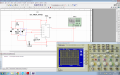
hi i designed a pulse width modulator using 555 the problem
is that the magintide is not stable,i simulated the circuit in multisim and with a breadboard using osciloscope plz can someone help me?
 

Attachments

wayneh

Joined Sep 9, 2010
18,104
I honestly don't know how to get that output from a 555. Scope the voltage on the timing capacitor. Maybe it will yield a clue.
 

jpanhalt

Joined Jan 18, 2008
11,087
same picture both locations :) playing around with that circuit now and it works like a charm
Which "both." Obviously, the schematic I posted and the schematic in the link for its source are the same, as one would expect.

However, the schematic posted by the TS is different. Look at the output/gate drive. In the TS's design, the "output" (Pin3) is used presumably for the gate drive, at least that is the source for the oscilloscope trace. In the DPRG design, "Discharge" (pin7) is used. Pin 7 is used in several designs as an output, but it is not the same as pin 3.

John
 

wayneh

Joined Sep 9, 2010
18,104
I'm still at a loss to explain how you could get that trace on the output pin of a 555. I would say it's a measurement artifact (such as a shifting ground) but the OP says the simulator gives the same result.
 

tom_s

Joined Jun 27, 2014
288
Which "both." Obviously, the schematic I posted and the schematic in the link for its source are the same, as one would expect.
thanks John, deem my interpretation of 'A common and different version is here:' incorrect

i read as A common (as image displayed) and assumed and different version is here: as another version.

kind regards,

Tom
 
Top