Pwm to MOSFET

Thread Starter

scam313

Joined Jul 19, 2022
44
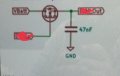
We are studying ISO transients and are building a load box. This load box has an N channel MOSFET and 47nF capacitor. The input will be 13.5 volts and up to 1.4 amps. The output will be wired to a connector to a harness that will be connected to a circuit board with 40 LEDs and the duty cycle is 65pct. How would I go about wiring the pwm and Vbat? I attached a small schematic. I am thinking about using VN2210 for the FET but maybe I should use something different?
 

Attachments

Thread Starter

scam313

Joined Jul 19, 2022
44
Not an actual assignment but an experiment on my end. Using some of the college equipment to apply to what we have studied.
 

Alec_t

Joined Sep 17, 2013
15,119
The input will be 13.5 volts
Do you mean the voltage at the FET drain?
Are you aware the gate voltage needs to be about 10V more positive than the source voltage if the FET is an ordinary N-channel type (not a logic-level one) and is being used as a switch?
 

Thread Starter

scam313

Joined Jul 19, 2022
44
Ya my power supply is 13.5v so I should use a smaller FET? Wouldn't PWM go to the gate and Vbat to the drain, the source pulled to ground?
 

Thread Starter

scam313

Joined Jul 19, 2022
44
Should use a P channel mosfet and connect the PWM to the gate directly if the voltage is high enough or through a npn or n channel mosfet if logic level.
My 13.5 should go to the drain and ground to source correct. Should I put a resistor on the gate after the pwm wire?
 

Thread Starter

scam313

Joined Jul 19, 2022
44
The pwm is being provided by a generator so my wire will just be connected to a banana jack in the box for plug in
 

sghioto

Joined Dec 31, 2017
8,634
Your diagram in post #1 shows high side switching which requires a P channel mosfet but if the load is just for LEDs you can use a
N channel and switch the low side. Here is an example of each type.
What is the voltage output of the PWM generator?
1689033096339.png
 

Thread Starter

scam313

Joined Jul 19, 2022
44
Well on the output of the box which is connected to a wire harness there is a circuit board with a few led drivers that are driving the LEDs, I will check the generator in the morning. Thanks
 

sghioto

Joined Dec 31, 2017
8,634
Well on the output of the box which is connected to a wire harness there is a circuit board with a few led drivers that are driving the LEDs, I will check the generator in the morning. Thanks
Pwm generator is max 10v
In this case I would choose high side switching using a IRF9Z24NPBF, P channel mosfet or similar.
 

Thread Starter

scam313

Joined Jul 19, 2022
44
Pwm generator is max 10v
In this case I would choose high side switching using a IRF9Z24NPBF, P channel mosfet or similar.

Would the configuration still be the same as low side because I am not supposed to put more than one FET into the box?
 

Thread Starter

scam313

Joined Jul 19, 2022
44
The arb will generate a max output of 0-10V at any PWM.
the transistor output which will be the PWM gated 13.5V battery signal with the 47nf cap to ground.
The circuit should be taking a steady DC signal and PWMing it out, not opening and shorting it to ground.
 

Thread Starter

scam313

Joined Jul 19, 2022
44
Only supposed to use one FET or trans with an output cap for transient hold up capacitance.with pull up resistor possibly as long as it's not pulling pwm to ground
 
Last edited:
Top