I hope that the reason is because it's a proportional valve.
Hey Geo, if this solenoid is not designed to be a proportional solenoid, and you're trying to apply PWM to it to make it behave like one, prepare yourself for disappointment. Proportional solenoids/valves are designed a certain way, to respond in a linear way to a linear current in their coils. Ordinary solenoids are NOT. As you raise the current through an ordinary solenoid (via PWM, or other methods) to the point it starts to move, it moves all the way, and that's that. If you were to try to control it proportionally, you would need some position feedback and a VERY tight control, and even then probably wouldn't work. Hence why they make proportional solenoids the way they do.
Yeah, and a 30A solenoid is a big one. A 30A proportional solenoid is bound to be "one...expensive...beast..." Which is why I question what we are dealing with here. I would expect to find a 30A proportional solenoid valve somewhere along the Alaskan pipeline; not on someone's garage workbench. Seems someone who could afford a valve like that wouldn't be fiddling around with Mosfets; they would just order the appropriate kilobuck proportional valve controller from the valve manufacturer.
*i can't help but assume its on a valve. Just how my brain is wired. It might be a linear actuator or something
** but, if it were a valve, it seems something that large would be pilot operated and not require 30A. Now im curious. What is this thing?
In any case a very large proportional valve is operated by a low current pilot spool, never seen one controlling the main spool that large.
Also placing a reverse diode across a solenoid of that current will retain it at 50hz cycle time, it certainly wont't be pulsing.
Max.
Yeah typically. typically it would be a hydraulic or pneumatic valve and the pilot fluid comes from the system fluid, which is the same fluid that the valve is metering. But what if it were an explosive gas valve or a crude oil valve? Crude oil for pilot fluid? I doubt it. So they would need a separate hydraulic circuit just to support this one valve. Maybe its cheaper to just make a giant direct-acting proportional valve for stuff like pipeline applications.
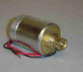
I will look for the part number on the solenoid . Here is a similar picture of what it look like.
I believe it is a plunger type solenoid that is linear.
And from what I understand it is a 30A solenoid but without the data sheet I cannot confirm this.
Essentially what this solenoid does is activate a reverse clutch only when you are in a chosen forward low gear.
Therefore it would have both forward clutch and reverse clutch activated when the solenoid is activated. I would want to pwm the solenoid so that the reverse clutch will only "creep or slip" just a bit.
Me too. I would be very surprised indeed if it worked. But I think this is still worth the time trying, if you have the time. It's an excellent exercise with Lots to be learned about mosfet switching, pwm, and solenoids. It's only a failure if nothing is learned, and I think you're well past that.
So the pulse rate must be slow enough so that the plunger is actually stroking in and out?
That solenoid likely has an inductance measured in Henrys (or a sizable fraction thereof), so the pulse rate would have to be like 0.5Hz to 2Hz?
This hasn't made sense to me from the start, but now I'm picturing the solenoid barely moving but cycling from "pushing hard" to "just starting to retreat". I'd have to see it to believe it.
Seems to me that it could work to use the solenoid at full force and, instead of trying to pulse it, adjust its applied force by a lever with an adjustable mechanical advantage.
This hasn't made sense to me from the start, but now I'm picturing the solenoid barely moving but cycling from "pushing hard" to "just starting to retreat". I'd have to see it to believe it.
Me too. I would be very surprised indeed if it worked. But I think this is still worth the time trying, if you have the time. It's an excellent exercise with Lots to be learned about mosfet switching, pwm, and solenoids. It's only a failure if nothing is learned, and I think you're well past that.
Yes I'm going to keep trying until I get it to work. The MOSFETs should get here today and I am thinking about buying an Arduino from the local Radio Shack and using that as my PWM.
From what I have read you can program the duty cycle and frequency with a laptop instead of rotary switches.
Yes I'm going to keep trying until I get it to work. The MOSFETs should get here today and I am thinking about buying an Arduino from the local Radio Shack and using that as my PWM.
From what I have read you can program the duty cycle and frequency with a laptop instead of rotary switches.
Yes arduino is very handy. It can do exactly what you want, although it is a bit overkill for just generating a pwm signal. I say buy it anyway. It is a great into to programming and electronics.
This hasn't made sense to me from the start, but now I'm picturing the solenoid barely moving but cycling from "pushing hard" to "just starting to retreat". I'd have to see it to believe it.
Seems to me that it could work to use the solenoid at full force.
Right!! The concept is to have the solenoid at full force then hitting it with the pwm and having the plunger just slightly release the reverse for 1second. Fine tuning it would be with both the duty cycle and the frequency.
I wired everything up yesterday and had some success! I used only one of the MOSFETS and it seems to be holding up fine, the MOSFET never once heated up.
The solenoid pulses the way I want it to. Now its to the fine tuning part of it.
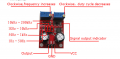
This is the adjustable 555 that I am using. The blue adjustable pots do seem to get hot once I turn or increase the duty cycle. Also the solenoid only pulses at certain frequency's, part about it is that with this timer I'm kind of shooting in the dark as far as to where I set the frequency, as of now its on the 1Hz-50Hz setting. I use the built in LED as a guide.

 Facebook
 Google
 GitHub
 Linkedin