Need help with a pulsed solenoid driver

Thread Starter

Soop

Joined Feb 10, 2022
21
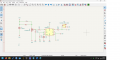
This is going to sound counter intuitive, but I have put this (circuit pictured) together on a breadboard, and I cannot get it to work, even just turning an LED on without anything to do with the solenoid.

The chip is a TLC 555, one of which has just overheated, and what I want it to do is switch on a solenoid for about 50 ms when a switch is pressed. This is a custom circuit for a Namco arcade gun (Point Blank etc).

When pin 2 is pulled low, pin 3 should then pull the Gate high on the Mosfet (IRLZ44N).

then for now, I'm just testing at 5v with the source connected to ground, and an LED connected to a resistor connected to 5v before I involve the solenoid and 24v.

Shorting pin 2 to ground should light the LED for ~50ms, right? pin 6 and 7 should control the timing. But it just doesn't light up at all. I guess it's possible the mosfet is dead, but can anyone verify that the design should work and that I'm not missing something?
 

Attachments

Thread Starter

Soop

Joined Feb 10, 2022
21
ah thanks all. There was originally supposed to be a 10n cap between pin and ground, but I didn't have one to hand, so I took it out. Can someone explain what practical difference it makes? I do now have 10n caps, but they're tiny SMD components and I hate them
 

Thread Starter

Soop

Joined Feb 10, 2022
21
also, for what it's worth, the LED thing was user error. I'm not used to working with breadboards, and I'd introduced a short. Time to put it back together again (tomorrow)
 

crutschow

Joined Mar 14, 2008
38,314
There was originally supposed to be a 10n cap between pin and ground, but I didn't have one to hand, so I took it out. Can someone explain what practical difference it makes?
It filters any power supply noise that could cause timing variations.
That's unlikely to be a factor in your application, so pin 5 can be left open.
 

Thread Starter

Soop

Joined Feb 10, 2022
21
It filters any power supply noise that could cause timing variations.
That's unlikely to be a factor in your application, so pin 5 can be left open.
perfect, that suits me just fine. And you're right, the timing isn't critical here
 

Mussawar

Joined Oct 17, 2011
157
ُین
ah thanks all. There was originally supposed to be a 10n cap between pin and ground, but I didn't have one to hand, so I took it out. Can someone explain what practical difference it makes? I do now have 10n caps, but they're tiny SMD components and I hate them
Pin5 "control voltage" pin is internally tied to internal voltage reference and should be decoupled through a small capacitor. Practically you can use 0.01 to 0.1uF or even larger values but don't leave it floating.
Pin 5 could also be used to control the timing via a potentiometer in monostable, bistable or astable modes without disturbing RC network.
 

Thread Starter

Soop

Joined Feb 10, 2022
21
ُین

Pin5 "control voltage" pin is internally tied to internal voltage reference and should be decoupled through a small capacitor. Practically you can use 0.01 to 0.1uF or even larger values but don't leave it floating.
Pin 5 could also be used to control the timing via a potentiometer in monostable, bistable or astable modes without disturbing RC network.
what happens if pin 5 is left floating? What are the consequences? Good to know about the pot adjustment.
 

crutschow

Joined Mar 14, 2008
38,314
Pin5 "control voltage" pin is internally tied to internal voltage reference and should be decoupled through a small capacitor. Practically you can use 0.01 to 0.1uF or even larger values but don't leave it floating.
what happens if pin 5 is left floating? What are the consequences?
In this application I see no problem with leaving Pin5 open.
Any timing variation due to circuit noise is unlikely to cause a variation in the 555 timeout sufficient to be a problem in this application.
 
Last edited:

Mussawar

Joined Oct 17, 2011
157
what happens if pin 5 is left floating? What are the consequences? Good to know about the pot adjustment.
Capacitor at pin5 is used to decouple the internal voltage reference. Consider it a ripple filter. If pin 5 is left floating, it will disturb (noisy) the internal 2/3 VCC reference. This reference is used to drive internal discharge transistor. By using a potentiometer you can set your own threshold reference which will affect overall timing cycle. You can find numerous diagrams around the web. While using a potentiometer, you still need a capacitor for decoupling.
 

crutschow

Joined Mar 14, 2008
38,314
Capacitor at pin5 is used to decouple the internal voltage reference. Consider it a ripple filter. If pin 5 is left floating, it will disturb (noisy) the internal 2/3 VCC reference.
The internal "reference" is just three 5kΩ resistors in series between power and ground (supposedly the source of its 555 designation).
The two voltages from this resistive divider are the Threshold and Trigger levels.

Pin 5 is connected to the junction of the two top resistors, giving a Thevenin impedance of about 3.33kΩ, thus it's unlikely that significant noise would be picked up by pin 5 if left unconnected.
The reason for decoupling that pin is to suppress any power supply noise that could affect the pulse time in sensitive timing applications.
 
Last edited:

Thread Starter

Soop

Joined Feb 10, 2022
21
ok, my PCBs arrived today, and everything is more or less working, but my prototype testing seems to have been incomplete (I was mostly testing with an LED on the same 5v circuit for convenience).

I had assumed that the pulse generated by the 555 would drive the solenoid and release it, even if the switch was held. This is not the case, and the solenoid is held as the switch is held. Space is already quite sparse, does anyone know of a simple way to ensure one press = one timed pulse until release? I understand a schmitt trigger would do what I'm asking, but I don't think I have the space for an IC, maybe not even transistor. Could a small inline capacitor work for me here on the conductor towards the switch?
 
Top