 Facebook
 Google
 GitHub
 Linkedin
Hi everyone,
since some time i am fighting with this driver, i need to control a blower (hvac), it is brushed motor, inrush current bit lower than 18 amps, pwm from PIC running at 20 kHz. I've try with some chineses H Bridge (using only half), single mosfet, parallel mosfet, always fries after few minutes. I have a basic osciloscope ( hantek measure DC only?)
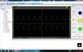
in the pictures, yellow line is source PWM (after driver IR4427) and green on the motor (measure mosfet drain, inverted probe), this driver was the last, with H bridge there were clean flat signal on motor.
PIC uses soft start (low duty cycle and increase slowly until desired duty)
what am i failing ? ???
since some time i am fighting with this driver, i need to control a blower (hvac), it is brushed motor, inrush current bit lower than 18 amps, pwm from PIC running at 20 kHz. I've try with some chineses H Bridge (using only half), single mosfet, parallel mosfet, always fries after few minutes. I have a basic osciloscope ( hantek measure DC only?)
in the pictures, yellow line is source PWM (after driver IR4427) and green on the motor (measure mosfet drain, inverted probe), this driver was the last, with H bridge there were clean flat signal on motor.
PIC uses soft start (low duty cycle and increase slowly until desired duty)
what am i failing ? ???
Attachments
-
 185.6 KB Views: 21
 -
 157.3 KB Views: 20
 -
 157.8 KB Views: 15


