PWM circuit to dim an LED

jpanhalt

Joined Jan 18, 2008
11,087
Part of maturing is being able to evaluate the advice you receive and/or data you read. Learn to read the attachments. Advice without links/citations is as valuable as advice at the fish market about high-tech stocks.
 

Thread Starter

Mellisa_K

Joined Apr 2, 2017
391
Part of maturing is being able to evaluate the advice you receive and/or data you read. Learn to read the attachments. Advice without links/citations is as valuable as advice at the fish market about high-tech stocks.
Yes I think that is very good advice for a learner like me. Thankyou.

Your metaphor is a suitably strong one!
 

Thread Starter

Mellisa_K

Joined Apr 2, 2017
391
It is not smart to overlook the other contributors (even if trying to be polite) = take time to digest all the provided input you will likely have a lot more questions . . . other than that -- you are dealing with quite high power here

so you must pay attention dealing with "open circuitry" (i usually power the circuitry under TEST - below 200mA - through the multimeter appropriate current range - as one possibility to stay aware what's going on and relay on ?250mA fuse internal to Ammeter)

you also don't want to bend brake the wire attachments to your led module (it's complicated and perhaps destructive to LED module to re-solder these)

ask questions here or perhaps Quora before you attempt something you're not sure about
___________________

i'm likely to exceed your input tolerance here ...

about soldering the heat sink terminals (pg. 20 , 21) (is why you may want to avoid this)
+ common information:
https://www.digikey.com/en/articles...junction-temperature-in-lighting-applications
https://www.digikey.com/en/articles/techzone/2011/oct/advances-in-led-thermal-management
https://www.digikey.com/en/articles/techzone/2011/nov/understanding-and-preventing-led-failure
https://www.digikey.com/en/articles...g-the-cause-of-fading-in-high-brightness-leds
https://www.digikey.com/en/articles/techzone/2011/oct/identifying-the-causes-of-led-efficiency-droop
Re yr alert to pages 20 and 21:
Yes, I have learnt to avoid SMD components at least for the time being. I don't have the equipment and my poor eyesight means I have magnification issues to solve compounding my sinexperience with the SMD work. Too many problems before I even start.

My reluctance to take on SMDs underlies my attraction to the hacking option. In this case, the LEDs are pre-mounted presenting me with pre soldered dangling wires to solder. It's a good trade off for me in this case between cost and convenience. 4_All_compnents.jpeg
 

Thread Starter

Mellisa_K

Joined Apr 2, 2017
391
It is not smart to overlook the other contributors (even if trying to be polite) = take time to digest all the provided input you will likely have a lot more questions . . . other than that -- you are dealing with quite high power here

so you must pay attention dealing with "open circuitry" (i usually power the circuitry under TEST - below 200mA - through the multimeter appropriate current range - as one possibility to stay aware what's going on and relay on ?250mA fuse internal to Ammeter)

you also don't want to bend brake the wire attachments to your led module (it's complicated and perhaps destructive to LED module to re-solder these)

ask questions here or perhaps Quora before you attempt something you're not sure about
___________________

i'm likely to exceed your input tolerance here ...

about soldering the heat sink terminals (pg. 20 , 21) (is why you may want to avoid this)
+ common information:
https://www.digikey.com/en/articles...junction-temperature-in-lighting-applications
https://www.digikey.com/en/articles/techzone/2011/oct/advances-in-led-thermal-management
https://www.digikey.com/en/articles/techzone/2011/nov/understanding-and-preventing-led-failure
https://www.digikey.com/en/articles...g-the-cause-of-fading-in-high-brightness-leds
https://www.digikey.com/en/articles/techzone/2011/oct/identifying-the-causes-of-led-efficiency-droop
you also don't want to bend brake the wire attachments to your led module (it's complicated and perhaps destructive to LED module to re-solder these)
I
 

crutschow

Joined Mar 14, 2008
38,579
However, I now have a dilema: Each AAC member's suggestion is quite different and I have no way of evaluating one from the other
That can be a problem.
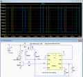
I will possibly add to the confusion on that, but here's what I think is one of the simpler solutions for an adjustable PWM control of the LED.
It uses a 555 astable timer with adjustable duty-cycle and a transistor LED driver.

The LTspice simulation is shown below.
The yellow trace is the LED current with the pot (U2) set near maximum brightness, and the blue trace is for the pot set near minimum brightness.
(D3 is the LED and R2 is the resistor that I believe is already in series with the LED).

upload_2019-8-11_18-55-42.png
 
Last edited:

Thread Starter

Mellisa_K

Joined Apr 2, 2017
391
Sorry about the repeated quote just now without my reply. I am clumsily still coming to grips with replying to posts on the AAC website when i want to refer to a single sentence.

You said:
"you also don't want to bend brake the wire attachments to your led module (it's complicated and perhaps destructive to LED module to re-solder these)"

I say:
Yes, you've alerted me to the need to secure the leads at the point of the SMD aluminim heatsink contact. I will put two blobs of heat glue a these points to anchor the wires and stop them spinning on the soldered joint.
 

Bernard

Joined Aug 7, 2008
5,784
#25, is R2 really necessary? Added cost for any benefit. Already has something close to heat sinked 5 ohm R. Presume LEDs are white and all in parallel?
 

Thread Starter

Mellisa_K

Joined Apr 2, 2017
391
#25, is R2 really necessary? Added cost for any benefit. Already has something close to heat sinked 5 ohm R. Presume LEDs are white and all in parallel?
I think he might be referring to the baked in resistor on the aluminium SMD board? See my pic in #23
 

Thread Starter

Mellisa_K

Joined Apr 2, 2017
391
That can be a problem.
here's what I think is one of the simpler solutions for an adjustable PWM control of the LED.
It uses a 555 astable timer with adjustable duty-cycle and a transistor LED driver.

1) This is self triggering. Its therefore known as astable, yes?
2) That means the reset pin #8 is connected directly to the positive voltage source Vcc, (=pin 8), yes?
3) q2 is necessary because you havent drawn the connecting lines to #8 and #4. Why didnt you draw these? something to do with convention?
 

crutschow

Joined Mar 14, 2008
38,579
1) This is self triggering. Its therefore known as astable, yes?
Yes.
2) That means the reset pin #8 is connected directly to the positive voltage source Vcc, (=pin 8), yes?
Pin 8 is the power pin.
But yes, both pin 4 (reset) and pin 8 go directly to power (from the on/off switch).
3) q2 is necessary because you havent drawn the connecting lines to #8 and #4. Why didnt you draw these? something to do with convention?
I have no q2, so don't know what you are referring to.
I didn't draw the connecting lines for all the power connections to minimize drawing clutter.
They are all labeled as node V+ and the convention is that all nodes with the same label are connected together, the same as all nodes with the ground symbol are connected together.
 

Thread Starter

Mellisa_K

Joined Apr 2, 2017
391
Yes.
Pin 8 is the power pin.
But yes, both pin 4 (reset) and pin 8 go directly to power (from the on/off switch).
I have no q2, so don't know what you are referring to.
I didn't draw the connecting lines for all the power connections to minimize drawing clutter.
They are all labeled as node V+ and the convention is that all nodes with the same label are connected together, the same as all nodes with the ground symbol are connected together.
My ambiguity. q2 refers to my second question labelled not "q2" but "2)". Sorry. I also just realised Q# also by convention refers to IC output pins. Shows how precise one needs to be in these fora
 

crutschow

Joined Mar 14, 2008
38,579
I also just realised Q# also by convention refers to IC output pins.
Q# typically is used as a reference designator for transistors.
IC output pins are usually designated with an abbreviation of their function.
Shows how precise one needs to be in these fora
Yes, you need to learn the jargon of electronics to effectively communicate on these forums. :)
 

ci139

Joined Jul 11, 2016
2,008
To tell you the truth I was trying to be polite to each one. I want to justify each one's trouble and kindness by thanking them and acknowledging their efforts.
(there was 10+ ways to get it as not "my correct" . . . in Estonia we work and don't much thank each other . . . also we have a proverb here that "A pig needs to be fed , a fool need to be praized " :eek: is why i complained , ;) hi-hi)
two blobs of heat glue
? become a mind reader (or then it's quite trivial solution) ((i haven't seen such a sahrp person for quite a while :confused:))
+ if you managed to somewhat familiarize with everything we threw at you - you'd be smarter than me already (coz i'm a lazy cat actually , muhahahahaa)
++ confusion is normal at this point (they show at Viasat in the ?"mind games"? how the mind "automatically" associates untyped data using later added context e.g. "The mouse on the table is broken " ?? "The mouse is snatching chips on the ? keyboard" ←src.(@ 17:27) ) . . . alike , blah,blaah...
 
Last edited:

Thread Starter

Mellisa_K

Joined Apr 2, 2017
391
Hi Mellisa,

Here's a link to a manufacturer who makes golf carts and other EV stuff. In its ealy (15 years ago) days, it was a wonderful resource for me.
http://www.4qdtec.com/pwmmod.html

The first two circuits shown are triangle/sawtooth to PWM, and the third is a 555-based circuit.
Hey jpanhalt, I am going to try the second circuit. Could you pls advise:
1) which resistor I should make into a potentiometer to alter the dimming
2) what voltage VCC

Many thanks

Mellisa
 

Thread Starter

Mellisa_K

Joined Apr 2, 2017
391
That can be a problem.
I will possibly add to the confusion on that, but here's what I think is one of the simpler solutions for an adjustable PWM control of the LED.
It uses a 555 astable timer with adjustable duty-cycle and a transistor LED driver.

The LTspice simulation is shown below.
The yellow trace is the LED current with the pot (U2) set near maximum brightness, and the blue trace is for the pot set near minimum brightness.
(D3 is the LED and R2 is the resistor that I believe is already in series with the LED).

View attachment 183693
Thanks again crutschow. I made this and it works well! Moreover it seems to work on any LED I throw at it! I'm very encouraged. Encouraged enough to work my way through other designs from the kind AAC member's in this thread. (thank you all)
 

Thread Starter

Mellisa_K

Joined Apr 2, 2017
391
If you dont want to do any programming, the easiest method if to use something like a 555 timer to create the PWM signal. You would then need to use this PWM signal to drive a transistor (low side MOSFET would be a good choice) connecting to the LED negative.

Here is a reference to get you started:
https://www.electroschematics.com/5834/pulse-generator-with-555/
Hey kuikmaa,
I made something very similar to this from a circuit provided by crutschow further down in this thread. I chose his to start with because that diagram was arranged according to the physical layout of the pins of the 555 IC and was much easier to for me to understand. If I was more experienced it wouldn't make any difference. Maybe one day! In the interim, I will try to juxtapose the two layouts to see how similar they are
 

Thread Starter

Mellisa_K

Joined Apr 2, 2017
391
A triangle wave oscillator circuit from NatSemi Linear Applications Handbook 1994, page 28:
View attachment 183555
View attachment 183556

For single supply operation, bias the grounded inputs to VCC/2. Opamp common mode input range will dictate minimum VCC.
Hi dl324,
This looks similar to a suggestion using opamp/comparator circuitry from jpanhalt in this thread. I am about to start his circuit and then I will compare with yours. I

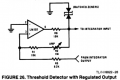
the interim would you be so kind as to post Fig 26 from your source. It's referred to in the penultimate paragraph in the text describing Figure 25 in your post. When I get that I'll be in a better position to learn from the comparison of your circuit with jpanhalt's.
Thanks again
Mellisa
 
Top