PWM circuit to dim an LED

Thread Starter

Mellisa_K

Joined Apr 2, 2017
391
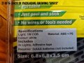
I want to hack an LED I bought in a cheap variety store. It has several surface mounted LEDs on a circular yellow disc. It runs on 3 X AAA batteries, wired in series.

My aim is to variably dim this LED using something other than a variable resistor.

I connected it to my power supply at 4.5 volts DC and it draws about 250mA of current.

I divided the voltage using a 25k potentiometer by connecting it in series between the positive side of battery and the positive lead to the LED. This works well but I am concerned at the inefficiency of this method. I want to replace the pot with something else that won't waste power from the battery.

I looked on the internet and found references to PWM as a means of more efficiently controlling
the voltage to the LED.

reference mentioned Arduino as the solution. I don't want to use a microcontroller. I want to use a hard wired circuit using active electronics components like ICs and transistors. That way I can get a better understanding of how it works.

Can you help me design a PWM circuit for this?

What else can I tell you about my project to start you off?
 

ci139

Joined Jul 11, 2016
1,898
( answer only what you can tell by quick visual inspection = no disassembly required ) . . . ? number of leds ? are they connected in multiple - parallel-series-strings ? limitting resistor(s) (value or marking if smd) ? anything product code/-model/-pcb.rev. ← would allow to estimate rated I.fw for single led or the exact product you have in hand ←← that would be lot of help for further decisions ...
 

Thread Starter

Mellisa_K

Joined Apr 2, 2017
391
If you dont want to do any programming, the easiest method if to use something like a 555 timer to create the PWM signal. You would then need to use this PWM signal to drive a transistor (low side MOSFET would be a good choice) connecting to the LED negative.

Here is a reference to get you started:
https://www.electroschematics.com/5834/pulse-generator-with-555/
Thankyou so much kuikmaa for your quick response.

Looks great. I've used 555 in an earlier project. I'll give it a go.

The output side of the oscilator still needs some specs. You mentioned a transistor between the pulse and the LED postive side.

Could you show me exactly what to do with it please. Maybe a sketch of this part of the circuit.

I'd like to know it all before I start please.
 

Thread Starter

Mellisa_K

Joined Apr 2, 2017
391
( answer only what you can tell by quick visual inspection = no disassembly required ) . . . ? number of leds ? are they connected in multiple - parallel-series-strings ? limitting resistor(s) (value or marking if smd) ? anything product code/-model/-pcb.rev. ← would allow to estimate rated I.fw for single led or the exact product you have in hand ←← that would be lot of help for further decisions ...
Understood. I will take apart and post photos. Doubt there I'veare markings. Ive got a cool microscope that connects to my PC. Takes pics.

It'll take a day or so to get back to you.
 

dl324

Joined Mar 30, 2015
16,909
A triangle wave oscillator circuit from NatSemi Linear Applications Handbook 1994, page 28:
upload_2019-8-9_9-18-21.png
upload_2019-8-9_9-18-39.png

For single supply operation, bias the grounded inputs to VCC/2. Opamp common mode input range will dictate minimum VCC.
 

kuikmaa

Joined Mar 23, 2019
10
Thankyou so much kuikmaa for your quick response.

Looks great. I've used 555 in an earlier project. I'll give it a go.

The output side of the oscilator still needs some specs. You mentioned a transistor between the pulse and the LED postive side.

Could you show me exactly what to do with it please. Maybe a sketch of this part of the circuit.

I'd like to know it all before I start please.
The easiest implementation is to use an NMOS between the LED and ground, being driven by the PWM signal:
upload_2019-8-9_13-5-45.png

You may not need that resistor, as it sounds like it already exists, since youre only drawing ~250mA @ 5V. Just choose a mosfet that can handle the current, and can be driven with the PWM voltage (likely will be 5V in your system).

You could also replace the MOSFET with a BJT, but will need to add a series resistor on the base.

Hope this helps,
Andrew
 

Thread Starter

Mellisa_K

Joined Apr 2, 2017
391
The easiest implementation is to use an NMOS between the LED and ground, being driven by the PWM signal:
View attachment 183560

You may not need that resistor, as it sounds like it already exists, since youre only drawing ~250mA @ 5V. Just choose a mosfet that can handle the current, and can be driven with the PWM voltage (likely will be 5V in your system).

You could also replace the MOSFET with a BJT, but will need to add a series resistor on the base.

Hope this helps,
Andrew
Got it thanks Andrew
 

Thread Starter

Mellisa_K

Joined Apr 2, 2017
391
( answer only what you can tell by quick visual inspection = no disassembly required ) . . . ? number of leds ? are they connected in multiple - parallel-series-strings ? limitting resistor(s) (value or marking if smd) ? anything product code/-model/-pcb.rev. ← would allow to estimate rated I.fw for single led or the exact product you have in hand ←← that would be lot of help for further decisions ...
Hello ci139,
I took five snaps sequentially homing in on its innards1_LED_Packaging.jpeg 1_LED_Packaging.jpeg 1_LED_Packaging.jpeg 4_All_compnents.jpeg 5 All components-Underside.jpeg
 

Attachments

ci139

Joined Jul 11, 2016
1,898
https://www.catch.com.au/product/super-bright-cob-click-on-light-3-pack-2689912/
Model no.: 81724
https://www.bmstores.co.uk/products/eveready-cob-push-lights-3pk-329566
(no useful information listed)
https://www.overstock.com/Lighting-...ion-Pod-Lights-Set-of-3/19683995/product.html
Model Number EM1767 Country of Origin India
__________
estimating led parameters ... 3AAA average internal resistance ≈ .54 3x = 1.62 + 3Ω limiting resistor = 4.62Ω · 250mA = 1.155V drop on internal resistance + limiting resistor → 4.38V (3×1.46V apx. full terminal voltage for AAA,AA) - 1.155V = 3.225V drop on LED → × 0.25A = 800mW or greater wattage led
so ... LED ::
  • I.F = ? 250mA
  • V.F = 3.2 .. 3.3 V (this actually varies per led - they are not so similar)
  • P.max ≥ 800mW (the actual value is not known at this point)
____________
related material about COB LED-s
________________
random related material ::

 
Last edited:

Thread Starter

Mellisa_K

Joined Apr 2, 2017
391
https://www.catch.com.au/product/super-bright-cob-click-on-light-3-pack-2689912/
Model no.: 81724
https://www.bmstores.co.uk/products/eveready-cob-push-lights-3pk-329566
(no useful information listed)
https://www.overstock.com/Lighting-...ion-Pod-Lights-Set-of-3/19683995/product.html
Model Number EM1767 Country of Origin India
__________
estimating led parameters ... 3AAA average internal resistance ≈ .54 3x = 1.62 + 3Ω limiting resistor = 4.62Ω · 250mA = 1.155V drop on internal resistance + limiting resistor → 4.38V (3×1.46V apx. full terminal voltage for AAA,AA) - 1.155V = 3.225V drop on LED → × 0.25A = 800mW or greater wattage led
so ... LED ::
  • I.F = ? 250mA
  • V.F = 3.2 .. 3.3 V (this actually varies per led - they are not so similar)
  • P.max ≥ 800mW
Thankyou ci139. I understand how you got those specs. Very clearly elaborated.
Thanks.
 

ci139

Joined Jul 11, 2016
1,898
It is not smart to overlook the other contributors (even if trying to be polite) = take time to digest all the provided input you will likely have a lot more questions . . . other than that -- you are dealing with quite high power here

so you must pay attention dealing with "open circuitry" (i usually power the circuitry under TEST - below 200mA - through the multimeter appropriate current range - as one possibility to stay aware what's going on and relay on ?250mA fuse internal to Ammeter)

you also don't want to bend brake the wire attachments to your led module (it's complicated and perhaps destructive to LED module to re-solder these)

ask questions here or perhaps Quora before you attempt something you're not sure about
___________________

i'm likely to exceed your input tolerance here ...

about soldering the heat sink terminals (pg. 20 , 21) (is why you may want to avoid this)
+ common information:
https://www.digikey.com/en/articles...junction-temperature-in-lighting-applications
https://www.digikey.com/en/articles/techzone/2011/oct/advances-in-led-thermal-management
https://www.digikey.com/en/articles/techzone/2011/nov/understanding-and-preventing-led-failure
https://www.digikey.com/en/articles...g-the-cause-of-fading-in-high-brightness-leds
https://www.digikey.com/en/articles/techzone/2011/oct/identifying-the-causes-of-led-efficiency-droop
 
Last edited:

Thread Starter

Mellisa_K

Joined Apr 2, 2017
391
It is not smart to overlook the other contributors (even if trying to be polite) = take time to digest all the provided input you will likely have a lot more questions . . . other than that -- you are dealing with quite high power here

so you must pay attention dealing with "open circuitry" (i usually power the circuitry under TEST - below 200mA - through the multimeter appropriate current range - as one possibility to stay aware what's going on and relay on ?250mA fuse internal to Ammeter)

you also don't want to bend brake the wire attachments to your led module (it's complicated and perhaps destructive to LED module to re-solder these)

ask questions here or perhaps Quora before you attempt something you're not sure about
___________________

i'm likely to exceed your input tolerance here ...

about soldering the heat sink terminals (pg. 20 , 21) (is why you may want to avoid this)
+ common information:
https://www.digikey.com/en/articles...junction-temperature-in-lighting-applications
https://www.digikey.com/en/articles/techzone/2011/oct/advances-in-led-thermal-management
https://www.digikey.com/en/articles/techzone/2011/nov/understanding-and-preventing-led-failure
https://www.digikey.com/en/articles...g-the-cause-of-fading-in-high-brightness-leds
https://www.digikey.com/en/articles/techzone/2011/oct/identifying-the-causes-of-led-efficiency-droop
To tell you the truth I was trying to be polite to each one. I want to justify each one's trouble and kindness by thanking them and acknowledging their efforts.

However, I now have a dilema: Each AAC member's suggestion is quite different and I have no way of evaluating one from the other, because I don't have the electronics knowledge. I can't build them all and my only diagnostic tool is a multimeter and a regulated power supply - not yet for example an oscilloscope.

Your raising power needs of the circuit is probably my first evaluating clue. My entire rationale for rejecting the variable resistor option is to conserve power of the battery. The voltage source for both the LED and the dimmer circuit must be portable and no larger than 3 X AAs or perhaps AAAs or perhaps a 9v.

These constraints reflect physical space available in my project. And my project is a business idea about which I am secretive until I can prove my concept because I don't want to be beaten to the (market) punch.

My dabbling in electronics has in the recent past been confined to oscilltors with the help of AAC members. I must say I find oscilltors fascinating and to learn more about them using this current project is attractive for this reason. Being a similar application is a postive to spur my interest.

However, perhaps Arduino is the way to go after all due to power needs of the PWM vis a vis a microcontroller. I have built a couple of Arduino projects but coding is not one of my current learning objectives. My learning objective is electronics componentry.
 
Top