PWM circuit to dim an LED

Thread Starter

Mellisa_K

Joined Apr 2, 2017
391
Hello @Danko and @cmartinez

Please refer to post #99 (and after) of thread https://forum.allaboutcircuits.com/threads/pwm-circuit-to-dim-an-led.162198/page-5 I thought I had better start another thread.

I followed your suggestions. I have received the SMD parts above and am ready for your tutelage to hand solder them. I have, as suggested, also got an adaptor board for the driver (but not for the inductor); as well as 0.3mm solder and tweezers and magnifier.

So all set!

Mod Note: Post Merged with this Thread.
 
Last edited by a moderator:

cmartinez

Joined Jan 17, 2007
8,796
Excellent. You might try looking at some videos out there regarding this subject, there's a plenty. But you also might want to get started by practicing soldering SMT resistors and caps. The technique is pretty straightforward. Using 60/40 solder, lightly tin one of the pads on the PCB, and then using tweezers hold the part in place and press the iron's tip against both the part and the pad until they're both soldered. After that you don't need the tweezers anymore, just apply a bit of solder (less is more) to the other side of the part and its pad. Easy as that... although it requires a little practice. I normally set the iron at 525°F for that purpose.

The hard part comes when you need to use low temp solder for delicate components, such as ADC chips. But we can get to that later.
 
Last edited:

Thread Starter

Mellisa_K

Joined Apr 2, 2017
391
Excellent. You might try to look for some videos out tok thank you here regarding this subject, there's a plenty. But you might want to get started by practicing soldering SMT resistors and caps. The technique is pretty straightforward. Using 60/40 solder, lightly tin one of the pads on the PCB, and then using tweezers hold the part in place and press the iron's tip against both the part and the pad until they're both soldered. After that you don't need the tweezers anymore, just apply a bit of solder (less is more) to the other side of the part and its pad. Easy as that... although it requires a little practice. I normally set the iron at 525°F for that purpose.

The hard part comes when you need to use low temp solder for delicate components, such as ADC chips. But we can get to that later.
 

Thread Starter

Mellisa_K

Joined Apr 2, 2017
391
Thank you Cmartinez.

Could you advise how I mount the inductor pls. Refer as follows:

https://www.coilcraft.com/do3314.cfm

I need a specialised adaptor but I don't know what to Google. Can you help pls.

I assume there is an industry standard for all the various configurations of SMD packages and their respective adaptors. Perhaps there is a publication listing these?
 

cmartinez

Joined Jan 17, 2007
8,796
Thank you Cmartinez.

Could you advise how I mount the inductor pls. Refer as follows:

https://www.coilcraft.com/do3314.cfm

I need a specialised adaptor but I don't know what to Google. Can you help pls.

I assume there is an industry standard for all the various configurations of SMD packages and their respective adaptors. Perhaps there is a publication listing these?
Actually, you don't have to look far. Most smt devices include their PCB mounting footprint in their datasheets. Look it up.
 

jpanhalt

Joined Jan 18, 2008
11,087
Let me add a small variation and some detail. Most metal tweezers are magnetic and become easily magnetized. Some SMD parts will stick to them, which can make placing them on the board difficult. I use either a pair of metal tweezers that are not magnetic or plastic (non-static) tweezers for placing the parts approximately on the board..

The other change is that I do not use the tweezers for positioning or holding while soldering. I use a short length (about 3 inch) of thin music wire for final positioning and holding. Grind or file the end to remove burrs from cutting. I also make a slight taper. The wire provides some springiness. I hold slight pressure on the part and solder the tinned end first as described by cmartinez.

When I am doing lots of parts, I switch to gluing the small parts (e.g., resistors, caps, some 3-pin devices). I do not pre-tin any pad. Using the same wire, I put a very tiny dot (less than 0.1 uL) of cyanoacrylic glue (super glue) between the pads and position the parts. After waiting a little, I solder away. That can also be done for bigger components, e.g., IC's, but I usually don't have that many of them to do.
 

jpanhalt

Joined Jan 18, 2008
11,087
Music wire is made from high carbon steel and is cold formed to give a hard, but not brittle wire. It has very high tensile strength and is used for springs, musical instrument strings, and a variety of other things. One of its specifications as I recall is that it can be bent around itself without fracturing.

upload_2019-10-9_5-5-37.png

Source: https://en.wikipedia.org/wiki/Piano_wire

The use I am most familiar with is in model airplanes for landing gear and pushrods. I buy mine at local hobby shops. What you need is a wire that while a little flexible will spring back and not retain a set. One might call it "spring steel wire" too. It comes in coils and straightened pieces. You want a straightened piece, if possible.

I forgot to give the diameter I use. Mine is about 0.034" (1/32"). That is not critical.
 

cmartinez

Joined Jan 17, 2007
8,796
I forgot to mention that once I position the part on the pcb, I hold it in place while soldering by pressing it (and not by clamping them) down using the same tweezers.

John is right about magnetized tweezers being a nuisance.

I'm going to make a small video today later on and post it here, to more clearly illustrate this process.
 

Thread Starter

Mellisa_K

Joined Apr 2, 2017
391
I forgot to mention that once I position the part on the pcb, I hold it in place while soldering by pressing it (and not by clamping them) down using the same tweezers.

John is right about magnetized tweezers being a nuisance.

I'm going to make a small video today later on and post it here, to more clearly illustrate this process.
Thankyou very much @cmartinez
 

Audioguru

Joined Dec 20, 2007
11,248
The voltage from a battery drops as it is used. How soon will the voltage be so low that the LED does not light anymore?
Three AA alkaline battery cells are 4.5V only when brand new and they drop to 3V when the LED probably is very dim.

The current is too high to use little AAA cells or a 9V battery. The LED will dim by itself as the battery quickly runs down.

An ordinary old 555 has a minimum supply of 4.5V and probably does not work when your battery voltage has dropped a little. Use a LMC555 which is guaranteed to work when the battery has dropped to only 1.5V. But most Mosfets need a much higher gate voltage, usually 10V but some Mosfets are "logic level" and work when the gate is 5V.

Many opamps also do not work at your very low supply voltage.
 

Thread Starter

Mellisa_K

Joined Apr 2, 2017
391
The voltage from a battery drops as it is used. How soon will the voltage be so low that the LED does not light anymore?
Three AA alkaline battery cells are 4.5V only when brand new and they drop to 3V when the LED probably is very dim.

The current is too high to use little AAA cells or a 9V battery. The LED will dim by itself as the battery quickly runs down.

An ordinary old 555 has a minimum supply of 4.5V and probably does not work when your battery voltage has dropped a little. Use a LMC555 which is guaranteed to work when the battery has dropped to only 1.5V. But most Mosfets need a much higher gate voltage, usually 10V but some Mosfets are "logic level" and work when the gate is 5V.

Many opamps also do not work at your very low supply voltage.
Oh OK, well that changes things a little!

Many thanks @Audioguru
 

Thread Starter

Mellisa_K

Joined Apr 2, 2017
391
Actually, you don't have to look far. Most smt devices include their PCB mounting footprint in their datasheets. Look it up.
Yes, I did look it up before I posted but I was still stumped.

To elaborate:

SOIC to Dip SMT Adaptors

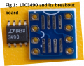
For the LTC 349 (datasheet attached "DS1") its pretty clear what I need. (Pls see Fig 1). Got it.
Fig 1 LTC349 and its breakout board.png

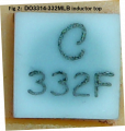
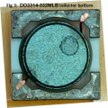
However for the SMT power inductor (DO3314 332 - see datasheet "DS2" attached) there are no feet to attach to such an adapter. Please see Fig 2 and Fig 3 below.
Fig 2 Inductor DO3314 332 Top view.png
Fig 3 Inductor DO3314 332 Bottom view.png

Do you know what SMT to DIP adaptor board I can use to get this inductor into my prototyping breadboard circuit?

Many thanks in advance

Mellisa
 

Attachments

cmartinez

Joined Jan 17, 2007
8,796
Yes, I did look it up before I posted but I was still stumped.

To elaborate:

SOIC to Dip SMT Adaptors

For the LTC 349 (datasheet attached "DS1") its pretty clear what I need. (Pls see Fig 1). Got it.
View attachment 187697

However for the SMT power inductor (DO3314 332 - see datasheet "DS2" attached) there are no feet to attach to such an adapter. Please see Fig 2 and Fig 3 below.
View attachment 187700
View attachment 187701

Do you know what SMT to DIP adaptor board I can use to get this inductor into my prototyping breadboard circuit?

Many thanks in advance

Mellisa
For devices such as those inductors, what I usually do is create a land pattern larger than the one recommended in the datasheet, and then proceed exactly as I would proceed with an SMT resistor or capacitor. That is, I'd make sure the solder touches the sides of its terminals. And in the inductor you're working with, that too is also possible because its terminals wrap up from the bottom to its sides, exposing a narrow area to which the solder can attach itself to.

Edit: The key is to press the iron's tip mainly on the PCB's pad and not directly on the side of the part. This to allow the heat (and thus the solder) to flow and find its way to the component.
 
Last edited:

cmartinez

Joined Jan 17, 2007
8,796
Do you know what SMT to DIP adaptor board I can use to get this inductor into my prototyping breadboard circuit?
To answer your question, I don't use adaptors, but rather I make my own PCBs using a process that I developed myself over the years.

Take a close look at these three links:

https://forum.allaboutcircuits.com/...ter-for-making-pcbs.110189/page-2#post-849894

https://forum.allaboutcircuits.com/threads/my-etching-process.115229/#post-898993

https://forum.allaboutcircuits.com/threads/my-new-etching-tank.117346/
 
Top