Facebook
 Google
 GitHub
 Linkedin
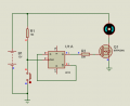
I like the circuit given by dl324 (post #8). I made my own copy of it. And for the sake of using this to control a fan, I've included the MOSFET dl324 mentioned in post #14. All I've done is take his drawing and put it together. Don't give me credit, I didn't draw this circuit; I just copied it. Because I like how elegant it is and how easily it will work.

Last edited: