Push On/ Push Off for 12v Power Supply

Thread Starter

TheLostRazgriz

Joined Sep 25, 2017
11
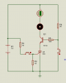
Hello, I only have a basic understanding of circuits and was wondering if I could get some help. I looked all over the internet but haven't been able to find just what i'm looking for. I'm trying to make a circuit to control cooling fans for a battery charger. The power supply is 12v and all of the fans draw several amps. I tried using a circuit that I found on YouTube, but it overheated due to the fact it was drawing several amps from a circuit designed for logic. I tried using a MOSFET controlled by the logic signal, but I couldn't get it to work properly. I have access to a lot of components, but only momentary push buttons as a means of switching. I was trying to avoid using a relay. I was wanting the button to toggle the power on and off. Any help will be greatly appreciated!
 

PeteHL

Joined Dec 17, 2014
475
Generally a battery charger for most of the charging cycle is charging at a constant rate. So it seems to me that if the charger includes a cooling fan, then that cooling fan needs to be operational for a large percentage of the time that charging is taking place. Further then there would seem to be little advantage to being able to turn off the cooling fan for the relatively short interval of the charging time period that the charger doesn't need to be cooled.

Maybe there is a good reason to control operation of the fan, but that isn't clear to me from your post.
 

Thread Starter

TheLostRazgriz

Joined Sep 25, 2017
11
Generally a battery charger for most of the charging cycle is charging at a constant rate. So it seems to me that if the charger includes a cooling fan, then that cooling fan needs to be operational for a large percentage of the time that charging is taking place. Further then there would seem to be little advantage to being able to turn off the cooling fan for the relatively short interval of the charging time period that the charger doesn't need to be cooled.

Maybe there is a good reason to control operation of the fan, but that isn't clear to me from your post.
We are doing this to cool down the batteries. There are no fans included in the battery charger. The 12v power supply and the battery charger are separate.
 
Last edited:

Thread Starter

TheLostRazgriz

Joined Sep 25, 2017
11
Your never going to find one that looks like that for high amperage. That type is used to trigger a relay for high amperage use. And have never seen that type in a push pull.
What if you use that to control a logic circuit that supplies a signal for the gate on a transistor? I just don't know exactly what transistor I need or how to make the logic circuit.
 

dl324

Joined Mar 30, 2015
16,943
What if you use that to control a logic circuit that supplies a signal for the gate on a transistor? I just don't know exactly what transistor I need or how to make the logic circuit.
You could use the 3 inverter circuit I posted in post #24 of this thread to convert the momentary switch to alternate action.

Use that circuit to drive a transistor that either switches the fan or controls a relay.
 

jayanthd

Joined Jul 4, 2015
945
I can help you with a simple PIC12F683 based PWM fan controller with one button to toggle ON/OFF of fan. One N-Channel Power Mosfet will be used (Logic Gate type).

I will give you firmware and C Code.
 

jayanthd

Joined Jul 4, 2015
945
Can you buy a PICKit 3 and program the PIC12F683 ? You can buy PICKit 3 Clone also.

I can give you a simple thyristor based circuit if you want. Mention the current rating of your Fan.

Is it a DC fan or AC fan ?

This is a rough circuit which I made. I have not calculated the exact resistor values.


Attachments

Last edited:

dl324

Joined Mar 30, 2015
16,943
What transistor would you recommend?
Something like IRF530 would work for driving the fans low side. It has an ON resistance of 0.15Ω at Vgs=10V and a maximum current of 14A. You could choose a device with a lower maximum current, at least twice the current you need.
 
Last edited:

AnalogKid

Joined Aug 1, 2013
11,056
Is this correct:

With a single, momentary, low current pushbutton switch, you want it to behave as an alternate action switch:
Press once - turns ON 12 Vdc power to fans
Press again - turns oOFF 12 Vdc power to fans
repeat

If that is correct, then the circuit is called a toggle flipflop. This can be done with two transistors, or a CD4093 CMOS quad NAND gate, o a CD4013 CMOS dual D-type flipflop, driving a power MOSFET transistor as the control device. What is the total current needed for the fans?

ak
 

Thread Starter

TheLostRazgriz

Joined Sep 25, 2017
11
Is this correct:

With a single, momentary, low current pushbutton switch, you want it to behave as an alternate action switch:
Press once - turns ON 12 Vdc power to fans
Press again - turns oOFF 12 Vdc power to fans
repeat

If that is correct, then the circuit is called a toggle flipflop. This can be done with two transistors, or a CD4093 CMOS quad NAND gate, o a CD4013 CMOS dual D-type flipflop, driving a power MOSFET transistor as the control device. What is the total current needed for the fans?

ak
Around 4.6 to 5 amps, if I need to, I could use 2 or 3 different systems to control different sets of fans
 

AnalogKid

Joined Aug 1, 2013
11,056
When it comes to CMOS gates and R-C circuits, things usually go better with Schmitt trigger inputs. The CD40106 is a hex Schmitt trigger inverter. You can use it for three independent circuits using this schematic from post #8:

upload_2017-9-25_16-47-25.png

You don't need IC1C for your application; IC1B can drive a power MOSFET directly.

Here is the version I use:

upload_2017-9-25_16-49-57.png

Same general idea but drawn differently, with an extra capacitor as a noise filter.

ak
 

Thread Starter

TheLostRazgriz

Joined Sep 25, 2017
11
When it comes to CMOS gates and R-C circuits, things usually go better with Schmitt trigger inputs. The CD40106 is a hex Schmitt trigger inverter. You can use it for three independent circuits using this schematic from post #8:

View attachment 135808

You don't need IC1C for your application; IC1B can drive a power MOSFET directly.

Here is the version I use:

View attachment 135809

Same general idea but drawn differently, with an extra capacitor as a noise filter.

ak
Thank you very much! I will build this tomorrow and let you know how it goes! What type MOSFET should I use?
 
Top