Pulse current to pulse voltage converter using TC4421

Thread Starter

newbies_hobbyist

Joined Jun 4, 2010
91
Hi,

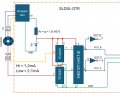
It's been a while since I started tinkering on electronics again. I have a question and requires experts answer. I have a three pin encoder where the output is in pulse current. I wanted to convert the pulse current signal (high <1.2mA, while low is >2.1mA) to pulse voltage. At first I was thinking of using an optocoupler but I couldn't find one that would work with between 1.2mA and 2.1mA. What I used instead is a mosfet driver TC4421 since this is what I have on hand. I thought it wouldn't work because as per datasheet, TC4421/22 requires a Vih 2.4V minimum and Vil of .8V to 1.3V, to my surprise, it worked fine. I want to understand why and how this driver worked despite of the input not within the specs. Links for encoder and TC4421/22 below, as well as the circuit converter. Thanks in advance.

TC4421/22
encoder
 

Attachments

Sensacell

Joined Jun 19, 2012
3,780
Your text and diagram do not match.
You state "3 pin encoder" - yet the diagram shows 5 connections?

Start with the actual part number of the encoder? it's a rotary mechanical unit?
 

MisterBill2

Joined Jan 23, 2018
27,315
I am lost at that description of the encode output. And certainly the circuits shown do not match the description at all.

So show us the circuit of the encoder to be used, not a guess at a replacement interface. In addition, the words about the output low and high make no sense at all without telling us the voltage and the load resistance.
OR is this an acquired encoder with no information provided??
I have successfully designed interfaces for quite a few encoders , and the description given does not make sense to me.
 

Thread Starter

newbies_hobbyist

Joined Jun 4, 2010
91
Your text and diagram do not match.
You state "3 pin encoder" - yet the diagram shows 5 connections?

Start with the actual part number of the encoder? it's a rotary mechanical unit?
Sorry for the confusion. It is s three wire encoder rotary encoder. As for the part number, you can find it here https://www.encoderonline.com/UK/Data-Sheets/Incremental/Data-AUX-DIN.htm

Updated the drawing. On the left side, that is the encoder and on the left side (inside the dashed red lines) is the converter.

Current to Voltage.jpg
 

Thread Starter

newbies_hobbyist

Joined Jun 4, 2010
91
I am lost at that description of the encode output. And certainly the circuits shown do not match the description at all.

So show us the circuit of the encoder to be used, not a guess at a replacement interface. In addition, the words about the output low and high make no sense at all without telling us the voltage and the load resistance.
OR is this an acquired encoder with no information provided??
I have successfully designed interfaces for quite a few encoders , and the description given does not make sense to me.
Sorry for the confusion. There is not much information about this encoder and so I don't have the circuit of it. I searched in internet but there is no diagram. The encoder info can be found here https://www.encoderonline.com/UK/Data-Sheets/Incremental/Data-AUX-DIN.htm

When the encoder output is less than 1.2mA the voltage output was held at 2.1V, when the encoder output is >2.1mA, the voltage output was held at 1V. From there on. So TC4421 is getting its input from encoder (1.2mA/2.1V, 2.1mA/1V). From the attached drawing, on the left side is the encoder, then on the right side (inside the red dashed lines) is the current to voltage converter. Like I said, I am getting the necessary output 0 and 5V and the receiver signal was able to correctly read this.
Current to Voltage.jpg
 
Last edited:

Sensacell

Joined Jun 19, 2012
3,780
Your circuit should not work.

The TC4421 is expecting a voltage input.
Your Encoder is outputting a current... (under what operating conditions?)

At the least, you need a resistor to convert the current signal into a voltage.
 

MisterBill2

Joined Jan 23, 2018
27,315
I followed that link and based on that description I WOULD NOT EVER CONSIDER THAT PRODUCT! OR that supplier!! The reason is that the description of the output is very incomplete.

Normally, current is dependent on both voltage and resistance.

Then i visited the linked site and I discovered that this is a product for use in hazardous areas, such as gasoline pumps. THat means that it must be INTRINSICLY SAFE! So the specifications shown are the maximum power to be safe so that there is not enough energy to produce a spark that could ignite an explosive vapor.

If the TS already has this encoder on hand, it should be possible to connect a voltmeter and rotate the encoder by hand and observe the output. Using an analog multimeter it should be possible to sense a voltage output.
Certainly there are additional specifications that would be more useful. The specifications provided are only for the safety aspect of the device. The additional parameters are only useful to folks actually needing to work with this device.

So now the next question is if the TS intends to use this encoder in an explosive vapor area, such as a gasoline pump or a natural gas meter??
 
Last edited:

Thread Starter

newbies_hobbyist

Joined Jun 4, 2010
91
I followed that link and based on that description I WOULD NOT EVER CONSIDER THAT PRODUCT! OR that supplier!! The reason is that the description of the output is very incomplete.

Normally, current is dependent on both voltage and resistance.

Then i visited the linked site and I discovered that this is a product for use in hazardous areas, such as gasoline pumps. THat means that it must be INTRINSICLY SAFE! So the specifications shown are the maximum power to be safe so that there is not enough energy to produce a spark that could ignite an explosive vapor.

If the TS already has this encoder on hand, it should be possible to connect a voltmeter and rotate the encoder by hand and observe the output. Using an analog multimeter it should be possible to sense a voltage output.
Certainly there are additional specifications that would be more useful. The specifications provided are only for the safety aspect of the device. The additional parameters are only useful to folks actually needing to work with this device.

So now the next question is if the TS intends to use this encoder in an explosive vapor area, such as a gasoline pump or a natural gas meter??
Hi Bill, you are absolutely correct about this type of encoder and yes I am intending to use this in a zone 2 environment and it is sealed as well. The maximum output I got from this encoder itself was 2.1V. Like I said, the current converter is doing its job, its just that I need to understand how at 2.1V coming from encoder makes the TC4421 able to detect this though the minimum input Vih required by TC4421 is 2.4V. Not really sure if it has something to do with the current coming out from encoder which is between 1.2mA and 2.1mA is enough to switch the input stage of TC4421.
 

Thread Starter

newbies_hobbyist

Joined Jun 4, 2010
91
Your circuit should not work.

The TC4421 is expecting a voltage input.
Your Encoder is outputting a current... (under what operating conditions?)

At the least, you need a resistor to convert the current signal into a voltage.
Hi Sensacell, I agree that it should not work based on TC4421 specs, apparently it is working. The maximum output of encoder itself is 2.1V, where the TC4421 minimum input Vih is 2.4V, yet it is conducting less than that. Not really sure if the output current of encoder (2.1mA and 1.2mA) is enough for the input of TC4421 to get activated. I was looking for any articles where TC4421 was used in a similar manner, unfortunately I couldn't find one. Anyway regarding the resistor, I tried this before but it didn't work, when I removed the resistor, then it worked. This is where I got surprised and scratched my head
 

MisterBill2

Joined Jan 23, 2018
27,315
Certainly the input to the converter will have some resistance for that current to pass thru. And current thru a resistor provides a voltage. That is "Ohms Law", which is seldom violated. If ever. The problem with the information presented is that it is provided trictly fo proving that the device is intrinsicly safe. That is fine, but by itself it does not help designing an interface circuit. But we do not design those because they still need to be certified and that is expensive. So folks just buy the module that is already certified and works.
 

Thread Starter

newbies_hobbyist

Joined Jun 4, 2010
91
Certainly the input to the converter will have some resistance for that current to pass thru. And current thru a resistor provides a voltage. That is "Ohms Law", which is seldom violated. If ever. The problem with the information presented is that it is provided trictly fo proving that the device is intrinsicly safe. That is fine, but by itself it does not help designing an interface circuit. But we do not design those because they still need to be certified and that is expensive. So folks just buy the module that is already certified and works.
Hi Bill thanks for the reply. Internal resistor or resistance in TC4421 is the only plausible explanation and I totally agree with you, however just for the sake of my curiosity I wanted to get others opinion about this. Anyway, without a more in-depth information about TC4421, my curiosity will remain. Again thank you so much for sharing your thoughts on this.
 
Top