Proteus Filter Design

Thread Starter

myil

Joined May 2, 2020
145
Hi Everyone,
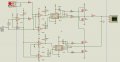
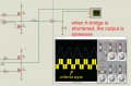
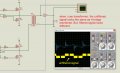
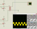
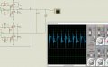
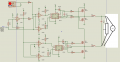
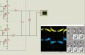
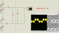
I am working on three level inverter.I found a good documentation on web and made the simulation on Proteus. But, now I am facing a problem with output filter. After the h-bridge, I add a low pass filter but the waveform looks like the photo I attached. I am expecting to get a sinewave output.But I couldn't. I am newbie on electronics. I would really appreciate your help.
 

Attachments

Does it work any better if you add a load after the filter?

You may want to also put diodes on each of the transistors to to deal with the inductive kick when the transistors are turning on and off.
 

Marc Sugrue

Joined Jan 19, 2018
222
Have you tried putting an actual load on your simulations as I don't see a load on any of your images - Only the filter.

Try putting a resistor on the output with the Ohm values based on the power you want to simulate.

Also you are assuming your L1 & C3 are pure inductance and capacitance but in reality will have ESR, ESL and parasitic components which will lower the Q in reality.

Without a load you look to be switching a resonant circuit hence the ringing.
 

Marc Sugrue

Joined Jan 19, 2018
222
Can you make a differential voltage measurement accross the bridge rather than a ground referenced Measurement? Ideally with a resistive load first. You should see an AC waveform (postive and negative cycles). The instruments your using look to be using Ground as the reference.

Put resistor between Q2 & Q4 Drain, remove the filter for now. And measure the voltage accross the resistor.
 

Marc Sugrue

Joined Jan 19, 2018
222
Is it possible for you to show how I can do it? I am sorry I am newbie on electronic :(
You've done well. See the attached image. The instruments your using has ground as the reference what you need is a differential measurement (i.e Floating) as what your interested in is the volts accross the load. Does proteus have a differential measurement option?
 

Attachments

Marc Sugrue

Joined Jan 19, 2018
222
Looks more like an inverter output. You still have the DC offset which says its still referenced to ground rather than differential accross the line. If it was a differential and your reference was on the horizontal center the output would go positive and negative. (above and below the line). It doesn't really matter as technically thats correct as there is a DC offset with respect to ground.

Now you can add your filter, I'd start with a balanced filter. So halve your inductance
 

Attachments

The function on the scope looks like A + B. Push the invert button on B to turn the equation into A - B.

i like to run the scope on DC coupling rather than AC, just in case something funny is going on. Probably will not have much of an effect here.
 

Marc Sugrue

Joined Jan 19, 2018
222
Ok, Are there reverse diodes in the Mosfet Models? If not you need to add some.

Then take a look at putting RC snubber accross your mosfets to disipate the ringing

Take a look at this schematic https://forum.allaboutcircuits.com/threads/filtering-an-h-bridge.152658/ To get an idea of placement. The issue you have is you are providing a switching waveform to inductors which are trying to keep the current flowing in you circuit but to do this they create a back EMF.
 
Top