Project: Scrolling LED display with out any controllers....

Thread Starter

RRITESH KAKKAR

Joined Jun 29, 2010
2,829
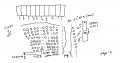
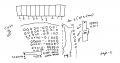
I have already posted whole circuit all block diagram. now if any one does not understand he may ask the question.
The hand dawn schematic contain all info exactly wht you want o know??
 

Wendy

Joined Mar 24, 2008
23,421
OK, a block diagram is not a schematic. A schematic has pin numbers on the components, with all the components shown, and how the entire diagram interconnect. There are short cuts with data lines, and repetitious circuits can be drawn in such a way it is understandable it is block X (pick a number) of the total.

I can build a complete circuit from a schematic, this can not be done with a block diagram. You should be at the level in electronics you can draw schematics. This is a critical skill for engineers and technicians alike.

A block diagram is a generalization, a schematic is very specific.


Where are the pin interconnects? there is a 4511 (or is it a 7447?) with no connections shown, with arrows going to displays that also show no pins. A schematic should not require me to go to a data sheet to figure out the chips pinouts. You also have a 12V power supply, which would eliminate TTL as a logic family.

I can help you document it, but it needs done for it to qualify.
 

Wendy

Joined Mar 24, 2008
23,421


I've started drawing a true schematic. Something is notably missing, where are your input buffers? The ones you store your numbers in. You also did not show any base resistors, not a good thing.

You will also need to provide a parts list, the values you showed for the 555 circuit were fantasy numbers.

*******************************************************************************
I am at a stopping point. I can not make heads or tails of your diode circuit. Need Schematics! I'm not too sure the above is correct either.
 

Attachments

Last edited:

Georacer

Joined Nov 25, 2009
5,182
If you didn't use a BJT, then how did you control the operation of the 7-segments. Clearly there is the idea of switching them on and off in the project. What would be the current-controlled switch if not a bjt?

If this kind of questions arise, then it is obvious that someone cannot replicate the project without having to re-design it.
 

Wendy

Joined Mar 24, 2008
23,421
There is no need of buffer..
Then show us how you did it. That is core to the problem I am having with this thread.

A beginner who knows schematics should be able to build this project from scratch with the information you provide. Problem is, you are not providing the information.

You didn't use transistors? Then what was this about?


I am trying to help. I have spent time trying to translate what you have into something usable, as shown by the schematic I have drawn. I am taking my best guess, which again, is core to the problem. I should not have to guess.

So now it is your turn, instead of telling us what you didn't do, take the time to draw what you did do.

One other thing, the images must be locally hosted. This means they must be uploaded to AAC as an album or an attachment. Your images are linked to your website.

The rules are clearly spelled out, we will help where we can to allow you to post on this forum. I am not trying to bust your chops. If you wish to abandon this it is no big deal to me, but if you want to display your projects you have to meet the requirements, and document the project. They are no less than a company will require of your designs in the future.
 

Attachments

Last edited:

Thread Starter

RRITESH KAKKAR

Joined Jun 29, 2010
2,829
I have not used BJT as current require was not so high for display i have show BJT in block just for an idea.

just for an idea

means :- if there will be discrete LED's more than one per segment..
then it is obvious it will require more current.
 

Thread Starter

RRITESH KAKKAR

Joined Jun 29, 2010
2,829
If you didn't use a BJT, then how did you control the operation of the 7-segments. Clearly there is the idea of switching them on and off in the project.
By directly connecting the output of 4017 to common pin of display (3and 8).
 

Georacer

Joined Nov 25, 2009
5,182
It must be the language barrier. Bill did try to communicate, I 'll give it a shot too.

I don't understand what the last batch of pictures you uploaded means, it may be because of my poor qualifications. But that's an even better chance for me to explain what is going on:

Suppose I am a complete newbie in electronics (which isn't very far away from reality). I stumble upon your scrolling LED display project and it looks so neat to me that I want to build one too.
If your project presentation were complete, it should include schematics (that is instructions) on how to exactly replicate what you built, without the need of you being by my side to guide me. Think about it as LEGO building instructions. Once you read them, you can build the project exactly as the author intended, to the last stud.

In the case of electronics, this is a bit different. Your project includes ICs and discrete elements, such as resistors. A complete schematic should depict exactly what is connected to what, pin by pin, nothing left unmentioned.

For example, in this schematic http://forum.allaboutcircuits.com/attachment.php?attachmentid=36801&stc=1&d=1322115265 there is no doubt about where the pins of the 4017 will be connected to. Moreover, those pins that must be connected have their pin number written on the outside of the IC and their meaning in the inside. The latter isn't necessary but it helps.
In your project, the 4017 pins are left leading in the air, ending in numbers that are repeated in the schematic. I, for one, do not understand where those pins should be connected to.

Can you understand now how a good schematic should be and why yours isn't one?
 

Wendy

Joined Mar 24, 2008
23,421
This...


is a partial schematic. It is not a block diagram. Block diagrams are aids in helping to understand a schematic, nothing more. They do not replace schematics.

It is unambiguous in how the circuit is wired. The missing part numbers would be covered in a BOM (Bill of Materials) later, as all the parts do have a part number associated with them.

This may indeed be a language issue, but drawing schematics is as absolute necessary technical skill for engineers and technicians. I am a technician by trade, the other moderators are engineers, or in school learning to become engineers. All of us know how to draw and read schematics, they are the true language of electronics. It doesn't matter if you speak English, German, or French, the schematic speaks for itself.

I will try to assist you in making a complete schematic if I can. I can clean up your drawings if needed to help them pass muster. But without a schematic this entry will not be complete or acceptable.
 

Thread Starter

RRITESH KAKKAR

Joined Jun 29, 2010
2,829
Hi,
But without a schematic this entry will not be complete or acceptable.
I am not worried about the entry......
Its all just because for explaining you.....not matter of entry.

Any way the above schematic is fine.
I will try to assist you in making a complete schematic if I can. I can clean up your drawings if needed to help them pass muster.
OK, now we have to connect the input of this 4011 (7447 driver) to output of all AND gate in a correct manner..!!
The above schematic is for scanning LED now we have to do the Changing message on vertical part. As i have indicated in my previous block.
by connecting at least to 4017 in series. The clock of that 4017 will be driven by scanning 4017 but after passing %10( divide freq by 10) in 4017 itself to low the switching freq

as indicated here.
 
Top