 Facebook
 Google
 GitHub
 Linkedin
Hi all
Have looking for a solution to the following problem without finding anything.
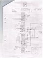
Have attempted to design a preprogrammed DOWN counter with 3 digits, seconds, 10 seconds and minutes.
Uses 3 x CD4510 and have problems with 10 second decade.
Problem 1, how to get 10 and one second to figure 59-00.
Problem 2, the ability to preset the counter at a selectable time.
Please see my link:
Regards
Lennart
Have looking for a solution to the following problem without finding anything.
Have attempted to design a preprogrammed DOWN counter with 3 digits, seconds, 10 seconds and minutes.
Uses 3 x CD4510 and have problems with 10 second decade.
Problem 1, how to get 10 and one second to figure 59-00.
Problem 2, the ability to preset the counter at a selectable time.
Please see my link:
Regards
Lennart
Attachments
-
 458.9 KB Views: 55


