 Facebook
 Google
 GitHub
 Linkedin
So the following is just code to try to turn on comparator interrupt. . For the micro controller PIC16(L)F1824
http://ww1.microchip.com/downloads/en/DeviceDoc/41419C.pdf
For the following code, the comparator 2 interrupt never triggers, as checked using breakpoints.
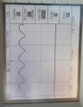
The attachment below shows the two inputs into the comparator. With the rectified ac going in on RC0/C2IN+ and the reference(which is close to but not zero) going in on RC1/C12IN1-. The comparator should fire while the rectified signal is great than the reference signal. Also by setting C2IF=1, the interrupt does occur. Yet the comparator doesn't do one itself. Where am I going wrong?
http://ww1.microchip.com/downloads/en/DeviceDoc/41419C.pdf
Code:
// PIC16F1824 Configuration Bit Settings

// 'C' source line config statements

// CONFIG1
#pragma config FOSC = INTOSC // Oscillator Selection (INTOSC oscillator: I/O function on CLKIN pin)
#pragma config WDTE = OFF // Watchdog Timer Enable (WDT disabled)
#pragma config PWRTE = OFF // Power-up Timer Enable (PWRT disabled)
#pragma config MCLRE = ON // MCLR Pin Function Select (MCLR/VPP pin function is MCLR)
#pragma config CP = OFF // Flash Program Memory Code Protection (Program memory code protection is disabled)
#pragma config CPD = OFF // Data Memory Code Protection (Data memory code protection is disabled)
#pragma config BOREN = ON // Brown-out Reset Enable (Brown-out Reset enabled)
#pragma config CLKOUTEN = OFF // Clock Out Enable (CLKOUT function is disabled. I/O or oscillator function on the CLKOUT pin)
#pragma config IESO = ON // Internal/External Switchover (Internal/External Switchover mode is enabled)
#pragma config FCMEN = ON // Fail-Safe Clock Monitor Enable (Fail-Safe Clock Monitor is enabled)

// CONFIG2
#pragma config WRT = OFF // Flash Memory Self-Write Protection (Write protection off)
#pragma config PLLEN = ON // PLL Enable (4x PLL enabled)
#pragma config STVREN = ON // Stack Overflow/Underflow Reset Enable (Stack Overflow or Underflow will cause a Reset)
#pragma config BORV = LO // Brown-out Reset Voltage Selection (Brown-out Reset Voltage (Vbor), low trip point selected.)
#pragma config LVP = ON // Low-Voltage Programming Enable (Low-voltage programming enabled)

// #pragma config statements should precede project file includes.
// Use project enums instead of #define for ON and OFF.

#include <xc.h>
#include <stdio.h>
#include <stdlib.h>
#include "pic16lf1824.h"

void main(int argc, char** argv) {

 TRISA = 0b00001011;//Set RA0/ICSPDAT,RA1/ICSPCLK and RA3/MCLR as input
 TRISC = 0b00000011;//Set RC0/C2IN+ and RC1/C12IN1- as input
 PORTA = 0x0;//Clear Port
 PORTC = 0x0;//Clear Port

 OPTION_REG = 0b00000000;//Set Prescaler to 1/2
 OSCCON = 0b01101000;//Set INTSOC to 4MHZ
 ANSELC = 0b00000011;//Set RC0/C2IN+ and RC1/C12IN1- as analog input
 INTCON = 0b11000000;//Enable Global and PIE Interrupt
 CM2CON0 = 0b10000000;//C1ON =1
 CM2CON1 = 0b00000001;//C2VP connects to C2IN+, C2VN connects to C12IN1-
 PIE2 = 0b01000000;//Comparator C2 Interrupt Enable

 while(1){}
}
void interrupt ISR()
{
 if(C2IF)
  {
     C2IF = 0;
  }
}
For the following code, the comparator 2 interrupt never triggers, as checked using breakpoints.
The attachment below shows the two inputs into the comparator. With the rectified ac going in on RC0/C2IN+ and the reference(which is close to but not zero) going in on RC1/C12IN1-. The comparator should fire while the rectified signal is great than the reference signal. Also by setting C2IF=1, the interrupt does occur. Yet the comparator doesn't do one itself. Where am I going wrong?
Attachments
-
 186.4 KB Views: 6

")


