Problem with osciloscope and signal

Thread Starter

Rokeeeez

Joined Feb 8, 2018
19
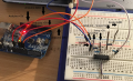
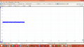
Hello, I have circuit with this amplifier, and with this circuit I amplify my pressure transducer signal from 30mV to 700mV. Amplifier works correctly, when applied pressure is increasing, multimeter shows higher voltage (range 700mV-1.3V). Both, transducer and amplifier are powered from Arduino 5V. Problem is that, when I connect scope cables to circuit output, voltage is decreasing to 500mV from 700mV (700 mV in multimeter) and when i applied more pressure to transducer, signal in scope still is about 500mV and there is no changes in signal, while there should be some increases in signal amplitude. (i attach photo with scope screen and my schematics).
 

Attachments

ebp

Joined Feb 8, 2018
2,332
There isn't enough information here for anyone to do anything but make guesses.

Exactly how is the oscilloscope connected? probe type, ground connection, other connections to the circuit

Does the signal as displayed on the meter drop when the ground of the probe is connected or only when the probe tip is connected?
 

Thread Starter

Rokeeeez

Joined Feb 8, 2018
19
Probe - 10x, all circuit on the breadboard, probe tip is connected to output of amplifier, the ground of the probe connected to breadboard ground (blue line). Signal drops, when the ground of probe is connected, when only the tip is connected, the signal don't dp.
 

ebp

Joined Feb 8, 2018
2,332
That helps a little. It suggests to me that something somewhere else is connected to a "ground" that is at different potential.

Is that a PC-based Picoscope?

Next step - with the probe completely disconnected, measure the voltage between the ground on your breadboard and the ground lead on the scope probe. If it is not zero, measure the current between the two - you might do this by connecting a low-value resistor (say 100 ohms) between the two and measuring the voltage across it.

Can you do a simple sketch that shows how everything is connected - a photo of a hand-drawn block diagram on paper would be fine. Be sure to include how each piece of the circuity gets its power and how the grounds are connected together. Include the scope.
 

Thread Starter

Rokeeeez

Joined Feb 8, 2018
19
That helps a little. It suggests to me that something somewhere else is connected to a "ground" that is at different potential.

Is that a PC-based Picoscope?

Next step - with the probe completely disconnected, measure the voltage between the ground on your breadboard and the ground lead on the scope probe. If it is not zero, measure the current between the two - you might do this by connecting a low-value resistor (say 100 ohms) between the two and measuring the voltage across it.

Can you do a simple sketch that shows how everything is connected - a photo of a hand-drawn block diagram on paper would be fine. Be sure to include how each piece of the circuity gets its power and how the grounds are connected together. Include the scope.
This is the circuit.
 

Attachments

Audioguru

Joined Dec 20, 2007
11,248
This circuit is on every website electronics chat forum. This is the first time that a photo shows the opamp ground pin 4 is not connected to its power supply ground. The opamp also does not have an important power supply bypass capacitor.
 

ebp

Joined Feb 8, 2018
2,332
Oops! Missed it by that much. Looks like there are other connection errors, too.

First lesson of using plug-in breadboards - when troubleshooting, probe devices on their pins, not in other holes in the breadboard. I've seen DIPs with a pin bent under the body - superficially looks like it is connected & it isn't.

That poor amp must have been getting its power via the protection diodes on the inputs through the bridge. I've seen CMOS logic work quite well when powered that way.

Differential amps, as opposed to instrumentation amps, degrade and load a bridge transducer. Compensation can usually be made, but care is required. [Edit - added following:] Using a crude digital supply for excitation of a bridge also degrades the performance. Do ardy-weenies use the +5V rail as a ref for the ADC?
 

Audioguru

Joined Dec 20, 2007
11,248
I am sorry that I wrongly said pin 4 instead of pin 11 because the notch on the IC was in a shadow. I am also sorry that I did not look at the datasheet and got pin 4 and pin 11 with the wrong polarity.
 
Top