Problem analyzing a resistor network

Thread Starter

artrasa

Joined Oct 21, 2024
5
Hi all,

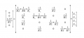
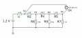
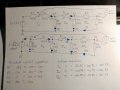
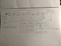
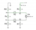
I just joined this forum. I'm having some problems analyzing the circuit shown below. I'm hoping to find a formula that relates the voltage "Ux" with the resistance "Rx".

The problem is that the resistance of Rx is unknown. Instead, the resistance of Rx should be calculated from the voltage difference (Ux) between the nodes N3 and N4. I'm unsure how to approach this problem, because (as far as I know) nodal analysis etc. requires all resistance values to be known in advance. This isn't the case here.

Any advice?
 

Attachments

WBahn

Joined Mar 31, 2012
32,702
In your diagram, is Ux a voltage source, or is it just a voltmeter?

There a many ways to solve the problem. One is to set everything up symbolically and then solve for the unknown quantities. If one of the resistances is unknown, then one of the voltages or one of the currents must be known instead. But you are given the current through R1.

Beyond that, you need to show your best attempt to work your homework as far as you can. We can then help you identify any mistakes you have made and help you take the next step so that you can continue.
 

Thread Starter

artrasa

Joined Oct 21, 2024
5
In your diagram, is Ux a voltage source, or is it just a voltmeter?

There a many ways to solve the problem. One is to set everything up symbolically and then solve for the unknown quantities. If one of the resistances is unknown, then one of the voltages or one of the currents must be known instead. But you are given the current through R1.

Beyond that, you need to show your best attempt to work your homework as far as you can. We can then help you identify any mistakes you have made and help you take the next step so that you can continue.
Ux is just a voltmeter measuring the voltage between nodes N3 and N4. I used Falstad's circuit simulator app for drawing the schematic. I re-arranged the components in my attached picture for a more understandable layout.

At first I tried to use nodal analysis to see if I could calculate the voltage across the unknown resistor Rx. But I'm unsure if it's the right tool for the job. Because Rx is not known during calculation time, there are unknown "1/Rx" elements in the conductance matrix (as shown in my attached picture). At this point I'm thinking nodal analysis might not be suitable for this particular problem.
 

Attachments

Thread Starter

artrasa

Joined Oct 21, 2024
5
It seems from your diagram that Rx is 3k7.
Please ignore the resistance value shown next to Rx as it is just a simulated value. In this problem the Rx value is unknown and it should be somehow calculated from the voltmeter's (Ux) reading. I'm still trying to figure out the way to achieve this.
 

WBahn

Joined Mar 31, 2012
32,702
Ux is just a voltmeter measuring the voltage between nodes N3 and N4. I used Falstad's circuit simulator app for drawing the schematic. I re-arranged the components in my attached picture for a more understandable layout.

At first I tried to use nodal analysis to see if I could calculate the voltage across the unknown resistor Rx. But I'm unsure if it's the right tool for the job. Because Rx is not known during calculation time, there are unknown "1/Rx" elements in the conductance matrix (as shown in my attached picture). At this point I'm thinking nodal analysis might not be suitable for this particular problem.
Is Ux one of the givens?

You aren't making it clear what is and what is not given as part of the problem statement.

How about presenting the problem statement so that we can see what, exactly, is given and what, exactly, is being asked for?

Nodal analysis if fine. The problem is that you are trying to take the nodal equations and then solve them using a matrix approach that only applies when all of the conductances are known.

But remember that matrix represents a system of equations. So take a step back and solve the system of equations it represents (i.e., forget about matrices).

You can also look at solving it other ways, too. Look at the information you are given. Can you use that to determine what the voltage across Rx is without doing a bunch of analysis? Can you get there by taking a bunch of baby steps? Given the information you have, can you find either the voltage or the current somewhere in the circuit? Once you have that additional information, can you then find another voltage or current somewhere?

You'll be surprised how easy this one becomes when you look at it through the eyes of electrical circuit principles and not from the standpoint of throwing memorized math techniques at it.

You might also consider getting an approximate answer by simplifying the circuit. Notice that the two 130 kΩ resistors are much, much larger than any other resistors in the circuit. What if you assume that they have little effect on things and Rx then? If so, then that should be within a few percent of the final actual value.
 

Jerry-Hat-Trick

Joined Aug 31, 2022
774
If you assume that the voltmeter has infinite resistance it's fairly easy to follow the circuit through to verify, based on the current into R1 and the voltage across the meter whether the value of Rx is 3K7Ω. If no current flows into the voltmeter then voltages at N3 and N1 are just ohm's law. Current lost through R8 means the rest of the current flows through Rx.

Coming at it from the other side, voltage at N4 is voltage at N3 less the voltage across the voltmeter. The current trough R7 would be the same as the current through R5 giving us the voltage at N2. This gave me a value of Rx of 3K9Ω. Either I made a mistake, or you can't assume the voltmeter has infinite resistance, and I haven't used R9. So it's a bit more complicated, but along these lines. A spreadsheet helps.
 

Yffig

Joined Aug 25, 2019
34
Rather defeats the purpose of a course trying to teach students circuit analysis concepts.
You may be right but if it's a student homework there is really no reason to give him the answer. Let's him do the work by himself, he'll learn a lot !
 

WBahn

Joined Mar 31, 2012
32,702
If you assume that the voltmeter has infinite resistance it's fairly easy to follow the circuit through to verify, based on the current into R1 and the voltage across the meter whether the value of Rx is 3K7Ω. If no current flows into the voltmeter then voltages at N3 and N1 are just ohm's law. Current lost through R8 means the rest of the current flows through Rx.

Coming at it from the other side, voltage at N4 is voltage at N3 less the voltage across the voltmeter. The current trough R7 would be the same as the current through R5 giving us the voltage at N2. This gave me a value of Rx of 3K9Ω. Either I made a mistake, or you can't assume the voltmeter has infinite resistance, and I haven't used R9. So it's a bit more complicated, but along these lines. A spreadsheet helps.
The problem, in the form given by the TS, is overspecified. There is one unknown resistance, so to make up for that, there needs to be either one given current or one given voltage. By giving one of each, we have more equations than unknowns and there will be no solution unless the voltage and the current happen to correspond to the same solution, in which case you can pick one and ignore the other and get the same result whichever one you pick.

This is why I asked the TS to tell us where these numbers are coming from. Are both the current in R1 and Ux given by the original problem? Is one the actual given and the other the result of his simulation when Rx is 3.7 kΩ? Or what?

As given, if you ignore Ux and work with the given current in R1, you get a particular value of Rx, but the resulting value of Ux is 791 mV. Since this is less than the given value of Ux, it can't be explained by the meter having a non-infinite resistance, since a finite resistance would lower Ux relative to the ideal case.
 

WBahn

Joined Mar 31, 2012
32,702
You may be right but if it's a student homework there is really no reason to give him the answer. Let's him do the work by himself, he'll learn a lot !
Which is why we aren't supposed to provide answers to homework problems, but rather provide guidance to help the student along the path of working the problem largely by themselves.
 

WBahn

Joined Mar 31, 2012
32,702
As can be seen from the following chart, the information given by the TS (the single dot above the line) is not compatible with the operating characteristics of the given circuit, which is the line that depicts the possible combinations of those two parameters.

1729882292402.png
If the 140.731 µA current is the given, then the voltage Ux is going to be ~791 mV. But if the 816.654 mV is the given, then the I1 current is going to be ~132 µA.

The values of Rx between these two points is ~500 Ω, or about 15%, so it's not a negligible descrepancy.
 

Thread Starter

artrasa

Joined Oct 21, 2024
5
Thanks for all your hints and advice. This is just a sensor circuit that I have been playing around in a circuit simulator. Its behaviour seemed interesting (very non-linear!) and I would like to see if I could find a formula or an equation that describes the relationship with the "known" voltage Ux and the "unknown" resistance Rx. Purely theoretical.

I tried to draw the circuit, in fact two versions of it with a voltage source and another with a current source. Hope it isn't too excessive. I'm basically learning by doing.

Given:
- Resistor values R1, R2, R5, R7, R8, R9.
- Voltage source E=1.2V.
- The voltage between nodes N3 and N4. Let's assume this is measured with an ideal voltmeter.

Find:
- how to calculate the unknown resistance Rx if we only know the voltage between nodes N3 and N4.

Thanks again for your help!
 

Attachments

WBahn

Joined Mar 31, 2012
32,702
Thanks for all your hints and advice. This is just a sensor circuit that I have been playing around in a circuit simulator. Its behaviour seemed interesting (very non-linear!) and I would like to see if I could find a formula or an equation that describes the relationship with the "known" voltage Ux and the "unknown" resistance Rx. Purely theoretical.

I tried to draw the circuit, in fact two versions of it with a voltage source and another with a current source. Hope it isn't too excessive. I'm basically learning by doing.

Given:
- Resistor values R1, R2, R5, R7, R8, R9.
- Voltage source E=1.2V.
- The voltage between nodes N3 and N4. Let's assume this is measured with an ideal voltmeter.

Find:
- how to calculate the unknown resistance Rx if we only know the voltage between nodes N3 and N4.

Thanks again for your help!
I would, once again, recommend starting with a simplified circuit that should yield results within a few percent of the actual results.

The two 130 kΩ resistors are so much larger than the other resistors in the circuit that they have only a minor effect. So remove them.

In doing so, you end up with a simple series circuit that is very easy to solve for Rx as a function of Ux.

Using this result, at Ux=791.4 mV you get a value for Rx that is 1.3% low and at Ux=816.7 mV you get a value that is 1.5% low. It's unlikely that the values of the fixed components are known to within that range, so this relationship is very likely more than good enough.
 
Ux is just a voltmeter measuring the voltage between nodes N3 and N4. I used Falstad's circuit simulator app for drawing the schematic. I re-arranged the components in my attached picture for a more understandable layout.

At first I tried to use nodal analysis to see if I could calculate the voltage across the unknown resistor Rx. But I'm unsure if it's the right tool for the job. Because Rx is not known during calculation time, there are unknown "1/Rx" elements in the conductance matrix (as shown in my attached picture). At this point I'm thinking nodal analysis might not be suitable for this particular problem.
Solve the matrix system and you will get complicated expressions for the voltages at N1, N2, N3, and N4. Form the equation (V(N3)-V(N4)) = Ux and solve for Rx. You'll get a complicated expression for Rx in terms of Ux and all the resistors. Substitute numerical values and for Ux = .816654 you'll get Rx = the neighborhood of 4k.
 

Thread Starter

artrasa

Joined Oct 21, 2024
5
I tried to solve the simplified circuit but I got something wrong as I got a constant expression for Rx. Perhaps my assumption that "U4 = Ux/2" simply does not hold. Or just some simple mistake.
 

Attachments

WBahn

Joined Mar 31, 2012
32,702
I tried to solve the simplified circuit but I got something wrong as I got a constant expression for Rx. Perhaps my assumption that "U4 = Ux/2" simply does not hold. Or just some simple mistake.
What is that assumption based on?

Since U4 is the voltage drop across R7, it is equal to current flowing through R7 multiplied by the resistance of R7.

Similarly, Ux is the voltage drop across the series combination of R2, Rx, and R5 and is therefore equal to the current flowing through them multiplied by the series resistance of R2, Rx, and R7.

Your assumption is only valid if R7 happens to be half the series resistance of R2, Rx, and R5.

Since R7, R2, and R5 are all known, that means that your assumption is only valid for one specific value of Rx, namely 600 Ω.

So, from a learning standpoint, you want to identify why you thought that U4 would be half of Ux and then make sure that you understand why there is absolutely no basis for this assumption.
 
Top