Pressure Sensor Realiability Control and Test

Thread Starter

ercngl

Joined Dec 17, 2018
4
Dear All,
I need your advice about a subject. Here it is;
I have pressure sensor which is used for the water level in washing machine.
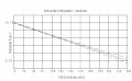
First of all, let me explain how a pressure sensor works. It is a circuit which uses pressure as input and gives square wave with variable frequency as output according to the pressure . So if the washing machine is empty, it produces 9.5 Hz frequecny, if it is 150mm full of water it produces 10.125 Hz and if the water machine is 300mm full of water it gives 10.75 Hz. So I want to check these values for being sure that they are correct. Here are the conditions;
1- If the water level is zero, empty, it produces 9.5 Hz so for example there must be a GREEN LED ON for this value. Otherwise there must be RED LED ON.
2- If the water level is half, 150mm, it produces 10.125 Hz so for example there must be a GREEN LED ON for this value. Otherwise there must be RED LED ON.
3- If the water level is full, 300mm, it produces 10.75 Hz so for example there must be a GREEN LED ON for this value. Otherwise there must be RED LED ON.
Do you have any idea about this kind of project or have you ever done this kind of work?
Do you think that I have to use a microcontroller?
I upload two images for the circuit of pressure stat and the graphich water level vs frequency.
Thanks in advance
 

Attachments

Alec_t

Joined Sep 17, 2013
14,280
Welcome to AAC!
Although it's theoretically possible to do this the analogue way with a frequency-to-voltage converter and comparators, the small frequency range might be a challenge. I think a MCU would be more appropriate for this project.
You need to define a distance range for each of the three scenarios. For example, what should happen when the water level rises to 5mm, or drops to 140mm, or ....?
 

Reloadron

Joined Jan 15, 2015
7,501
Well I'll be? Never saw one but LG Washing machines use a pressure sensor with a frequency out. This is interesting:
Understanding how the Water Level Sensor in LG Washing Machines work
The Water Level Frequency Sensor operation is based on the displacement of the *coil* attached to the diaphragm.

When the *coil* raises or lowers---it changes the electronically resonant characteristics of the oscillator circuit.

The water level is measured by the Main Board---by frequency readings.

I've never had a failed Water Level Sensor.

It is best tested while on the washer---by using the TEST MODE.

On most LG washers---the Test Mode is enabled by pressing and holding the SPIN SPEED and SOIL LEVEL buttons---and then pressing the POWER button (release all 3 buttons and wait for the door to lock).

Press the START / PAUSE button 4 times at one second intervals (Prewash Cold Water Fill)

The display read-out on the Control Panel will show the *frequency*

Empty---the frequency read-out should be about 255

A tub full of water should show a frequency of about 214 (depending on model number)

Some of the errors that can be displayed---relating to water fill are...

IE error:

Little or no water---usually caused by a failed Water Valve

FE error:

Too much water (overflow detected)---Can be a failed/stuck open Water Valve or blockage in the black air tube which is connected to the Water Level Frequency Sensor. Disconnect the tube from the sensor---and blow air back into the tub to clear obstruction.

To test the Water Level Frequency Sensor outside of the washer...

Use a test meter to check the ohms between pins 1 and 3 (should have between 21 & 23 ohms).
If you are building a test bench or test set for these things and plan testing hundreds of them you can either use a frequency to voltage converter and run the output voltage to a chip like an LM3914 which you can get on a board with LEDs.

Another option is to do as Alec covered and use a micro controller which could provide several outputs, including a readout of just about any data you want within any range you want. Really depends on exactly what you want.

Ron
 

Thread Starter

ercngl

Joined Dec 17, 2018
4
Dear All,
First of all, thanks for your attention.
I guess I need to use a microcontroller according to the advise from you.
Anyway, I will try tuo use an Arduino and I let you know how it goes.
Thanks
 

Reloadron

Joined Jan 15, 2015
7,501
Something you may want to think about and I have not tried this would be since your frequency range is very small between 9.5 Hz and 10.75 Hz measure the period. The period is Period = 1 / Frequency.

9.5 Hz = 0.10526 Sec
10.125 Hz = 0.09876 Sec
10.75 Hz = 0.0930 Sec.

Figure out your acceptable error range for your software. Also if this is going to be an ongoing test of these sensors you may want to include a low pass filter on the uC input.

Ron
 

MrChips

Joined Oct 2, 2009
30,711
While one may think that a microcontroller would be the easiest solution, there are other ways to skin this cat.
Why do you need green and red LED displays?

One solution has already been mentioned: a frequency to voltage converter followed by an LM3914 to LED array.
Why not skip the LEDs and use an analog voltmeter or a DVM for continuous readout?

I can also propose a simple circuit using two pairs of monostable multivibrators and four LEDs.

Is the signal already in the 0-5V logic range?
 

Thread Starter

ercngl

Joined Dec 17, 2018
4
While one may think that a microcontroller would be the easiest solution, there are other ways to skin this cat.
Why do you need green and red LED displays?

One solution has already been mentioned: a frequency to voltage converter followed by an LM3914 to LED array.
Why not skip the LEDs and use an analog voltmeter or a DVM for continuous readout?

I can also propose a simple circuit using two pairs of monostable multivibrators and four LEDs.

Is the signal already in the 0-5V logic range?
Dear MrChips,
The signal 5V square wave form and ranging from 9.5 Hz to 10.75 Hz. I never worked on monostable multivibrators but I check it out.
I want it to be simple and easy.
 

Reloadron

Joined Jan 15, 2015
7,501
I am sure Mr. Chips will be along with a good circuit or two.

You don't mention what exactly you want this circuit for. Things like will it be portable? Will you be testing many sensors looking for, just as an example, a pass fail criterion? If you are building a test stand or test fixture what do you plan to apply to the sensors? Maybe a calibrated pressure source? Since Mr. Chips has the analog circuit bases covered if you take a uC route I can give you some ideas using for example an Arduino Uno uC. As mentioned there are several ways to go about this.

Ron
 

MrChips

Joined Oct 2, 2009
30,711
The circuit I had in mind consisted of three monostable multivibrator circuits with individual trim-pot adjustments for the desired time periods as follows:

full = 93.022 ms
mid = 98.765 ms
empty = 105.263 ms

Since the ICs come with a pair of monostable circuits per package, there is the possibility of having four LED indicators.

Instead of having four trimpots to adjust, I present the following circuit with one trim-pot adjustment. The additional monostables are preset for incremental times from the first monostable. The D-type flip-flops latch the condition of the square-wave signal after the set duration. Note that the LEDs will flicker at 10Hz. The 4th LED is extra and can be used to indicate that the circuit detects SIGNAL IN.

The circuit contains:
(2) CD4538 or MC14538 Dual monostable multivibrator
(2) CD4013 or MC14013 Dual D-type flip-flop

Power supply is 3V to 18V. Adjust LED current limiting resistors R5-R8 for suitable LED brightness.

This circuit has not yet been tested and verified.

Washer Water Level.jpg
 

Thread Starter

ercngl

Joined Dec 17, 2018
4
Dear All,
I would like to thank you to all of you.
I started implementing circuit,so we will see how it works.
Thanks,
I let you know how it goes
 

MrChips

Joined Oct 2, 2009
30,711
Just a heads up to let you know that the circuit in post #10 is not quite right.

Do you know if the signal from the sensor is 50% duty cycle, i.e. the high and low duration are roughly the same?

Edit:
If SIGNAL IN is 50% duty cycle, here are the changes.
U1A pin-4 is connected to GND.
U1A pin-5 is connected to SIGNAL IN.
R1 = 390k
VR1 = 100k

If you are not too concerned with precise transition points you can substitute
R2 = 56k
R3 = 68k
R4 = 100k

If SIGNAL IN is not 50% duty cycle then I will make further accommodation.
 

MrChips

Joined Oct 2, 2009
30,711
The LED sequence is as follows:

FULL - LED D1
MID - LED D2
EMPTY - LED D3
BELOW EMPTY (signal detect) LED D4

Adjust VR1 for D1 to come on ( all LEDs ON) when FULL.
 

MrChips

Joined Oct 2, 2009
30,711
Here is the revised circuit if SIGNAL IN is 50% duty cycle. If it isn't I can provide another design.
The resistance values have been changed. Also the LEDs are driven from the Q-output of the D-type flip-flops.

This circuit has not yet been tested.

Washer Water Level ver_2.jpg
 
Top