Pressure sensor and amplifier difficulties

Thread Starter

Mark Flint

Joined Jun 11, 2017
145
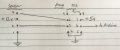
I'm using gas pressure sensor MPX2050GP with instrument amp AD623.

This is the documentation I'm referencing:
Sensor datasheet
https://www.nxp.com/files-static/sensors/doc/data_sheet/MPX2050.pdf

Amp (datasheet attached)
https://components101.com/ics/ad623-instrumentation-amplifier-pinout-datasheet

When I apply 12.32v to the sensor I read 4.74v from pin 2, and 4.08v from pin 4. This is at ambient pressure. This is the first thing that seems a bit mysterious to me - I thought the + and - outputs would be much lower.

The outputs go to pins 3 and 2 respectively on the AD623. The output from pin 6 reads about 1100mV at ambient pressure. When I apply 20 psi this output voltage increased by 35-40mV - which is what the sensor differential output is specifies as.

I think there's a possibility I have damaged the amp chip. Trouble is I'm not sure that the sensor is outputting correctly either.

Any tips would be appreciated.

EDIT: rough schematic now attached.
 

Attachments

Last edited:

ericgibbs

Joined Jan 29, 2010
18,849
hi,
I see that the AD623 is powered a single supply of 5V and the Vref pin is connected to 0v, so you will get about +500mV offset at the the AD623, when there is no differential input to the AD623.

For a balanced bridge with a 12Vdc excitation you would expect an output voltage of approx Vext/2 ie: 6V.
Checking the sensor d/s its possible that the nominal 4Vdc out is 'normal.

With the sensor disconnected from the AD623, what voltage do you measure from the sensor.?

E

EDIT:
Also measure the mV across the sensor output pins, when AD623 not connected.
 
Last edited:

Thread Starter

Mark Flint

Joined Jun 11, 2017
145
Eric, when I disconnect the amp I get 5.81v on each of the outputs from the sensor. This is with 12.30v supply.
 

ericgibbs

Joined Jan 29, 2010
18,849
Eric, when I disconnect the amp I get 5.81v on each of the outputs from the sensor. This is with 12.30v supply.
hi,
That sounds OK to me, ideally 12/2 = 6V.
Do you have a voltmeter with a mV scale, if Yes, measure across the sensor output pins, you should read close to zero mV, then apply some air pressure, there should be an increase in output voltage.
E
 

ericgibbs

Joined Jan 29, 2010
18,849
hi,
I problem I can see with your set up is the CMV [ common mode voltage] of 6V exceeds the 5 Vsupply to the AD623, this will cause a problem.

This is why you measure about 4V on the AD623 inputs.!!!
E


EDIT:

The AD623 can work with a maximum supply of 12Volts, try power it from 12V and remeasure the inputs with the sensor connected.
 
Last edited:

Thread Starter

Mark Flint

Joined Jun 11, 2017
145
Ah, I vaguely remember having that thought last night - but this morning there was no recollection!

Well, the sensor works just fine when measured across the two outputs on it's own. I've put 11.3 volts on both the sensor and the amp. Sadly the amp is now getting hot and the output (pin 7) is over 10v!

It might be time to order a new AD623.

Mark
 

ericgibbs

Joined Jan 29, 2010
18,849
hi Mark,
As I said, the AD623 is sinking the current from the sensor because the 6Volt common mode voltage exceeds the 5V supply to the AD623, so it will get warm. You may have 'cooked' the AD623 in your initial circuit.
Try the Gain pot set to give a gain of say of times one, and retry when the AD623 cools down.
E
 

Thread Starter

Mark Flint

Joined Jun 11, 2017
145
hi Mark,
As I said, the AD623 is sinking the current from the sensor because the 6Volt common mode voltage exceeds the 5V supply to the AD623, so it will get warm. You may have 'cooked' the AD623 in your initial circuit.
Try the Gain pot set to give a gain of say of times one, and retry when the AD623 cools down.
E
Eric, I have the same voltage on the amp as on the sensor - 11.3v. So the output from the sensor pins is now down around 5.5v while the input is 11.3v.
I'm not very good at reading datasheets, but on page 7 (table 4) of the attached file it seems to say the maximum input voltage is plus or minus 6v. What does that mean?
Thanks, Mark
 

ericgibbs

Joined Jan 29, 2010
18,849
hi,
That means it can be operated using +6V on +Vs and -6V on -Vs ie : a dual voltage.
It will aslo work with a single supply of 12V
+Vs=12V and -Vs =0
Check this clip from the d/s.
E
AA1 02-Nov-18 17.00.gif
 

Thread Starter

Mark Flint

Joined Jun 11, 2017
145
Ah, thanks for the explanation Eric.

I removed the resistor from across pin 1 and 8 - so no amplification. I let the chip cool and then restarted and measured about 3.5v on the output of the amp - and no noticeable change when I air pressure on. I think there's something wrong with my AD623 chip.
Cheers, Mark
 

ebp

Joined Feb 8, 2018
2,332
Note that the absolute maximum supply voltage for the amp is 12 volts (specified as ±6 V) - see Table 4 of the datasheet. Unless the power supply to be used is accurate and well regulated, it would be better to use a lower voltage. If a somewhat-dubious 12 V supply is available, 2 or 3 ordinary silicon PN diodes (1N4148, 1N400x, etc.) in series could be used to drop the voltage (about 0.6 to 0.7 V typically per diode). The pressure transducer is ratiometric, so the gain (dV/dp) depends directly on the supply voltage. This favors using a buffered voltage reference to supply the sensor if precision is required. For less critical applications, an adjustable 3-terminal regulator could be used.

It is very important that the amplifier is powered when the sensor is, otherwise potentially destructive current can flow into the amp inputs (which is probably what happened). See INPUT PROTECTION on page 17 of the datasheet (Rev D) for info on protection against this possibility.
 

ericgibbs

Joined Jan 29, 2010
18,849
hi Mark,
If you decide to reduce the 12V to the AD623, [ I have used 12V on many AD623 weigh scale projects without any problems] don't go below 10V, as that the recommended supply voltage for your pressure sensor.
Eric
 

Thread Starter

Mark Flint

Joined Jun 11, 2017
145
Note that the absolute maximum supply voltage for the amp is 12 volts (specified as ±6 V) - see Table 4 of the datasheet. Unless the power supply to be used is accurate and well regulated, it would be better to use a lower voltage. If a somewhat-dubious 12 V supply is available, 2 or 3 ordinary silicon PN diodes (1N4148, 1N400x, etc.) in series could be used to drop the voltage (about 0.6 to 0.7 V typically per diode). The pressure transducer is ratiometric, so the gain (dV/dp) depends directly on the supply voltage. This favors using a buffered voltage reference to supply the sensor if precision is required. For less critical applications, an adjustable 3-terminal regulator could be used.

It is very important that the amplifier is powered when the sensor is, otherwise potentially destructive current can flow into the amp inputs (which is probably what happened). See INPUT PROTECTION on page 17 of the datasheet (Rev D) for info on protection against this possibility.
Good points. I had been using a 240v to 12v LED driver to power the sensor, which then powers a buck converter to give 5v to the amp. The circuit right now has both the sensor and amp running off the buck convertor, adjusted to 11.3v. I wonder if the previous arrangement introduced a momentary time lag before the amp received power. I will now look at adding some current-limiting resistors in front of the amp inputs. Thanks!
 
Top