 Facebook
 Google
 GitHub
 Linkedin
Hi, everyone. I want to make a 3.5mm audio mixer so I can input from my guitar amp and my computer to my computer speakers. I found a description of one on http://www.circuitlib.com/index.php/tutorials/product/39-how-to-build-an-audio-mixer
with a few useful schematics.
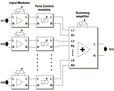
The above picture shows the overall mixer. I'm going to skip the tone control modules. I'm planning on breadboarding everything so I can add them later if I want. For now I only want input modules and the summing amplifier.

This is a picture of an input module with separate left and right channels.

And this is the summing amplifier.
I've got a few questions, mostly related to powering the op-amps. In both modules of interest, each op-amp only has one power channel shown. Should I assume that every op-amp has both +15V and -15V power lines, each grounded through a 100nF capacitor?
I'll need a +-15V power supply. Can anyone recommend something cheap? If not, I was thinking I could invert a +15V line from a standard 15V adapter with an op-amp and leave ground alone. Would that be noisy?
To split 3.5mm to left and right channels, can I just make contact at the tip and the middle section? Do I need audio ground for anything?

with a few useful schematics.
The above picture shows the overall mixer. I'm going to skip the tone control modules. I'm planning on breadboarding everything so I can add them later if I want. For now I only want input modules and the summing amplifier.
This is a picture of an input module with separate left and right channels.
And this is the summing amplifier.
I've got a few questions, mostly related to powering the op-amps. In both modules of interest, each op-amp only has one power channel shown. Should I assume that every op-amp has both +15V and -15V power lines, each grounded through a 100nF capacitor?
I'll need a +-15V power supply. Can anyone recommend something cheap? If not, I was thinking I could invert a +15V line from a standard 15V adapter with an op-amp and leave ground alone. Would that be noisy?
To split 3.5mm to left and right channels, can I just make contact at the tip and the middle section? Do I need audio ground for anything?
Last edited:


