 Facebook
 Google
 GitHub
 Linkedin
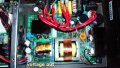
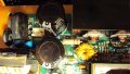
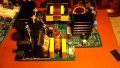
Hi all. Taken apart a carlsbro portable mixer amp T150 pa
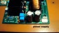
The power supply has gone down.
tested a few parts & replaced faulty ones. 2x fqp13n50's 1k resistor & 4007 diode
but it still won't power up ? all i get is the red led. not sure if its worth trying..
So going to replace. But the input to the amp says
32v+ grd 32v- the power supply i think is a switch mode ac to dc then through a
few fpq13n50 & isolator...
But can i put a 32v dc transformer onto the amp & is the ground in the middle of the 3 pins
32v+ gnd 32v- is this earth/case sorry but i can get a transformer but it's just + & -
pressume is 32v+ 32v- ...This will let me know if the amp is OK
If not then thinking of changing the amp & power supply
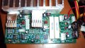
But will need to find out what voltage the mixer section runs on.
it is connected with a ribbon type cable. thin it's 5v as there is a 7805 reg & 7915 reg
there is no schematics for this unit so its a bit of a pain for me.
I'm not the best at working things like this out. any help would be great..
please view pictures if it helps.
chears jimbo
The power supply has gone down.
tested a few parts & replaced faulty ones. 2x fqp13n50's 1k resistor & 4007 diode
but it still won't power up ? all i get is the red led. not sure if its worth trying..
So going to replace. But the input to the amp says
32v+ grd 32v- the power supply i think is a switch mode ac to dc then through a
few fpq13n50 & isolator...
But can i put a 32v dc transformer onto the amp & is the ground in the middle of the 3 pins
32v+ gnd 32v- is this earth/case sorry but i can get a transformer but it's just + & -
pressume is 32v+ 32v- ...This will let me know if the amp is OK
If not then thinking of changing the amp & power supply
But will need to find out what voltage the mixer section runs on.
it is connected with a ribbon type cable. thin it's 5v as there is a 7805 reg & 7915 reg
there is no schematics for this unit so its a bit of a pain for me.
I'm not the best at working things like this out. any help would be great..
please view pictures if it helps.
chears jimbo
Attachments
-
 174.4 KB Views: 10
 -
 186.8 KB Views: 9
 -
 218.6 KB Views: 8
 -
 197.5 KB Views: 7
 -
 169.8 KB Views: 6
 -
 138 KB Views: 7
 -
 146.1 KB Views: 7
 -
 133.3 KB Views: 7
 -
 171.2 KB Views: 7
 -
 98.5 KB Views: 7


