Then there could be a variation in voltage due to inbalance.
But how often are unregulated voltages used where a small difference in that voltage is critical?
Then there could be a variation in voltage due to inbalance.
But how often are unregulated voltages used where a small difference in that voltage is critical?
Then there could be a variation in voltage due to inbalance.
But how often are unregulated voltages used where a small difference in that voltage is critical?
I am not sure if it makes any difference if we regulate the voltage or not. I have large caps on the output and it doesn't seem to matter.
I did a quick simulation and I see that with the ground close to the transformer we get a variation in the ground lead but it's a DC offset pulse it only goes positive (or just negative if the other load is made larger). That's interesting I think because we have only AC voltages present to drive the loads.
So the ground lead may go up by 100mv then down to 0mv, then back to 100mv then down to 0v again etc. This only happens with an imbalance in plus and minus loads, like 20 Ohms and 40 Ohms for example with a 10v output transformer (dual 10v windings connected as a center tapped lead).
This is a little more complicated though because we have to relate this to real life, and that means also considering how a regulator IC would handle this ground changing. It deserves some more thought. I know some audio amplifiers do it this way though, but I wonder if they know it can cause some extra noise, or if they have a way to mitigate that if it is really objectionable, and if the loads are imbalanced. I would guess that the loads are more balanced for that though because they depend on both supplies to power the output. It could be the imbalance is minor.
If I connect the ground at the output even through a larger resistor, I don't see any pulsing DC, just some small noise like 1nv or so. It looks random maybe due to the diodes switching.
It's funny though I can't remember all of the issues that come up now it's been many years since I've looked at one of these in detail. I remember one of the chief engineers saying something about it back in the 1980's but can't remember what was discussed.
It's looking at the voltage that develops across the ground lead running from the center tap to common of the loads. The common of the loads we would call ground, but for example if there is something else connected to the common closer to the center tap then there is a potential difference between the two common points. This is a very typical concern with power circuits, and some data sheets even show a thicker line drawn to show the connections.
The really strange thing is that the voltage developed is not a smooth DC, and it's not a sine wave either. It's a very strange looking wave with a peak that goes one way (like positive) and not the other way (negative). If it went down by as much as it went up, then at least it would average out somewhat.
The pulsed voltage may not be that large (100mv, 200mv, etc.) but the frequency could be 100Hz or 120Hz which shows itself as hum in audio circuits. It also wreaks havoc with ADC circuits.
It's also important to note that with some circuits it may not cause too much of a problem especially when the load is balanced. The problem outlined above is with a load that is different on the positive line than on the negative line (an imbalanced load).
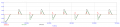
Here's a snapshot of the simulation.
The black and green line plots are the two currents out of the two transformer windings. The red line plot is the voltage across the ground line from the center tap to the load when the ground is placed at the transformer center tap. Note however that it is plotted as 10 times larger than it really is so that it can be seen along with the two transformer currents. It is really only about 100mv peak.
Also note that if we run the two leads that form the center tap directly to the load (after separating them), even with the same resistances in line we get no voltage like that except for a little tiny noise that is at a much lower level.
Some of the older audio amps that used tubes had a potentiometer for adjusting the hum. It was for a different reason, but it does show that hum is often a problem in audio amplifiers. I think back then the hum was due to the filament power source which was sine wave AC, and it would be 120Hz for a 60Hz power line.
 Facebook
 Google
 GitHub
 Linkedin