 Facebook
 Google
 GitHub
 Linkedin
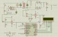
I have made a circuit in Proteus with the PIC16F887 for measuring the voltage, current , power and also power factor and display them on the LCD. In the circuit, the L1 and R5 can be any value as it is just a value for the load connected to the circuit.
I was wondering if I were to place some relays and capacitor in parallel with the load to correct the power factor, what changes would I need to make in the circuit and the source code?
PS: I have included the software and circuit in the Proteus file.
I was wondering if I were to place some relays and capacitor in parallel with the load to correct the power factor, what changes would I need to make in the circuit and the source code?
PS: I have included the software and circuit in the Proteus file.
Attachments
-
 45.8 KB Views: 101
 -
50.5 KB Views: 82


