Phasors are agnostic with regard to magnitude or RMS (or peak-to-peak, for that matter). The only differences are a scale factor, so it is important to know which convention is being used. Since these are linear circuits, you can assume one convention, work the problem, and then adjust afterwards if you find out a different convention is used (but remember that power is NOT a linear relationship, so you have to know what convention is being used to get the correct answer).
The only thing you can go from in that case is how phasors have been used in your text and in the course. If they have always referred to amplitude, then work it with them as amplitude. If that doesn't result in a result that matches what's offered, then work it assuming RMS values. The worst situation is if the author worked it both ways for the purpose of offering up detractors that you would get if you make the wrong assumption -- but then the author/instructor should have made efforts to emphasize that phasors are always to be interpreted a certain way.
i had verified that one of the results is the correct one.
A couple key points to think about:
1. What kind of component does the 0.7*j represent?
2. What do we know about that (#1) kind of component as far as power dissipation goes?
3. What is the only component (out of a choice of R, L, or C) that dissipates power?
4. How do we calculate power in that (#3) kind of component?
1. What kind of component does the 0.7*j represent?
Reactive
2. What do we know about that (#1) kind of component as far as power dissipation goes?
Reactive components, capacitor or inductor, don't dissipate any energy, ideally.
3. What is the only component (out of a choice of R, L, or C) that dissipates power?
R
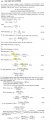
4. How do we calculate power in that (#3) kind of component? S=(I²_rms)(Z)=P+jQ. In case of R, it becomes S=(I²_rms)(R)=P
1. What kind of component does the 0.7*j represent?
Reactive
2. What do we know about that (#1) kind of component as far as power dissipation goes?
Reactive components, capacitor or inductor, don't dissipate any energy, ideally.
3. What is the only component (out of a choice of R, L, or C) that dissipates power?
R
4. How do we calculate power in that (#3) kind of component? S=(I²_rms)(Z)=P+jQ. In case of R, it becomes S=(I²_rms)(R)=P
The only thing you can go from in that case is how phasors have been used in your text and in the course. If they have always referred to amplitude, then work it with them as amplitude. If that doesn't result in a result that matches what's offered, then work it assuming RMS values. The worst situation is if the author worked it both ways for the purpose of offering up detractors that you would get if you make the wrong assumption -- but then the author/instructor should have made efforts to emphasize that phasors are always to be interpreted a certain way.
and my question was what component does the 0.7*j represent given the choice between a resistor R, a capacitor C, or an inductor L, so the three choices are either R, C, or L, so how can the answer be "reactive power" when that's not even a choice?
I am asking this because this is good to know.
Also good to know, what kind of component does the 0.05 represent, given the same three choices R, L, or C?
This is so you can get a view of the simplest intuitive representation of what an impedance might be made up of.
Another question that would help here is, do you know how to calculate the current through the entire 'load' impedance Z? That is the current you would measure with a real life current meter if you had this real circuit in operation on your work bench.
The part "0.7j" represents an inductive reactance.
The impedance is inductive when X is positive or capacitive when X is negative. Therefore, impedance Z = R + jX is said to be inductive or lagging since current lags voltage, while impedance Z = R - jX is capacitive or leading because current leads voltage.
Note that impedance is not a phasor.
Thank you.
PS: The problem has already be solved. Please check my previous posting. Thanks.
OK if you solved it that's great. I just wanted to point out that the impedance is just made up of components that we all know and love
And since we know one of them is a resistor, then we know the power dissipated only happens in that component alone, and if we could 'measure' the current through that component we could use i^2*R. Since we can calculate the current we would actually measure, we can use i^2R once we calculate that current, and that current is a real number.
When we see the whole picture we get a better idea how this stuff works, then we have a better iidea of how something else more complicated works, then something else even more complicated, etc. If we just use a formula, then when we are faced with a new situation it's hard to adopt to the new circuit because the formula may not cover that.
Could you please help me to understand the reason for introducing the factor of "1000" in eq. 4.4 and eq. 4.5?
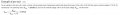
Eq. 4.4, Base current I_b = (1000)(MVA)_b/(kV) = (kVA)_b/(kV) A. It looks like as if "Mega" is converted into "kilo" by multiplying it by "1000" which doesn't make any sense. It looks like that 1000*Mega=kilo? Is it a typographical error? I don't think so because I checked another book too. Please see the attachment. Thank you for your help.
I did check the Wikipedia page and was able to understand 3-Φ calculation for I_base. I'm still struggling to understand the reason for introducing the factor of 1000 in that formula in my previous posting. Thanks.
 Facebook
 Google
 GitHub
 Linkedin
 24 KB Views: 7
")