PNP cascode current mirror instability oscillations output current issues troubleshooting

Thread Starter

franktyres

Joined Mar 4, 2025
16
Hello everyone,

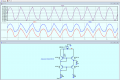
I'm working on calibrating a 4-20mA current loop and I am trying to stabilize the output current at 12mA using a cascode PNP current mirror. I’m using BC327-25 PNP transistors (unfortunately, I don’t know the exact manufacturer), and after testing, I found 4 of the transistors have an hFE value around 300.

I calculated the reference resistor (Rref) to be approximately 1870 ohms, based on my theoretical design. I assembled the circuit on a breadboard and used a precision ammeter to measure the output current (Iout), as well as the voltages across both Rref and Rload/out.

The issue I’m encountering is that the output current fluctuates around ±0.3mA, causing the output voltage to oscillate as well. The reference branch (Rref) is stable with no fluctuations, but the output side shows these oscillations.

I’ve double-checked the theoretical values and the design should work, but I’m unable to achieve the stability I need. Could anyone with experience in cascode PNP current mirrors offer insight on what might be causing these oscillations in the output? How can I stabilize the current to exactly 12mA?

Any help or suggestions would be greatly appreciated!

Thank you!

1741100661688.png
 

Thread Starter

franktyres

Joined Mar 4, 2025
16
I wanted to clarify that in my LTspice simulation, I did not include three 47pF capacitors, which are part of the actual physical circuit:

  1. One capacitor between the base and emitter of Q1.
  2. One capacitor between the collector of Q2 and ground.
  3. One capacitor between the collector and base of Q3.
I believe the simulation is correct, and it gives a result close to the 12mA output that I am aiming for. However, I would like to emphasize that the issue with the oscillations in the output current arises specifically in the real-world circuit that I built, not in the simulation. The output current in the actual circuit fluctuates by around ±0.3mA, causing the voltage to oscillate, while the reference side is stable.
 

Attachments

Thread Starter

franktyres

Joined Mar 4, 2025
16
Hi F,
The asc file shows this a link?
On the real World unit is the supply voltage 'clean' and stable?

E
Updated: Applied a fluctuating Vsupply
The supply voltage is clean and stable, i'm using a laboratory bench power supply, The capacitors were added later, on the suggestion of ChatGPT. I asked how to stabilize the circuit, and it gave me these indications. I felt it was unnecessary to update LTspice because I'm experimenting with the circuit design. In the future, I will have to create a PCB with quality components. For now, I'm building a test circuit to see if the idea is good and works. I encountered these problems, and I don't understand their nature and I want to understand them better.
 

Thread Starter

franktyres

Joined Mar 4, 2025
16
I think I should clarify that the oscillation is relatively slow—it takes several seconds, and it can take up to a minute for the current to fluctuate from 11.7 mA to 12.3 mA. Additionally, the trend isn't always consistent. Sometimes the oscillation is more pronounced, while other times it's less noticeable. At times, it can vary between 12 mA and 12.6 mA. The most common fluctuation is within the ±0.3 mA range, but it's not always limited to that.
 

panic mode

Joined Oct 10, 2011
4,864
12mA x 22V = 264mW for Q4... that is significant dissipation and probably deserves closer look at thermal effects. does the reading change faster if you touch Q4 by soldering iron or ice cube?
 

Ian0

Joined Aug 7, 2020
13,097
Hi F,
The asc file shows this a link?
On the real World unit is the supply voltage 'clean' and stable?

E
Updated: Applied a fluctuating Vsupply
That automatically produces a fluctuating input current, because Iin=(VSupply-2Vbe)/R
so you would expect a fluctuating output.
 

crutschow

Joined Mar 14, 2008
38,318
I would add a resistor or simple regulator in series with the supply to reduce the voltage, and thus power dissipation in the mirror transistors.
Heating of the transistors will cause a change in the output current.

Using dual matched-pair transistors will also reduce the temperature dependence.
 

panic mode

Joined Oct 10, 2011
4,864
so far the most likely culprits are identified as supply and temperature changes (self-heating of Q4).
the point is that one need to find the source of the noise... only then one can deal with it.

as others already stated, supply need to be clean and stable which is easy to check.
thermal drift can be confirmed by measuring temperature or introducing disturbance.

modeling noise (like supply fluctuations) is a good way to analyse problem and evaluate solutions.
here is a quick and dirty fix that helps reduce fluctuations caused by supply
1741109098384.png
 
Last edited:

crutschow

Joined Mar 14, 2008
38,318
here is a quick and dirty fix that helps reduce fluctuations caused by supply
Unfortunately that addition makes the mirror current sensitive to temperature.
A little less dirty is to use a TL431 or TLV431 in place of D1 and D2 with its REF input connected to the emitter of Q5 to generate a constant current.
That will both minimize the temperature variation, and also make the current more insensitive to power supply voltage variations.
 
Last edited:
Top