Please Help for de CTS/RTS/DCD/DSR/DTR pin of FT232RL

Thread Starter

allcircuits-sr

Joined Oct 4, 2019
8
Hello
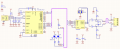
We used the FT232RL and ADM485 chips for the USB to RS485, but after 4 hours of continuous work, the FT232RL went wrong and we had to reconnect the converter from the USB port.
Could this be a problem with our design? In our design the RESET base and CTS, RTS, DCD, DSR, DTR basese of FT232RL chip are free and no connection!
Do we have to connect the CTS stand to the RTS stand and the DSR stand to the DTR stand and the DCD stand in the design? Is it better to connect these pins to each other to prevent FT chip error?
 

MrChips

Joined Oct 2, 2009
34,628
Did you design your own board or are you using a commercial adapter board?
Make sure that there are proper supply-rail decoupling capacitors on board.

Usually it is a bad thing to leave input pins floating. Read the device datasheet to find out if external pull-up or pull-down are needed.
 

Thread Starter

allcircuits-sr

Joined Oct 4, 2019
8
We have built this converter on one board. As a module. We have followed all the tips of .PCB.
We have used a 100nf capacitor for FT232RL and adm485 chips. And we also have a 4.7UF capacitor for USB voltage.
In this circuit, both chips are powered by 5V USB power.
Do we need to put a larger capacitor on the USB voltage?
Should we use a "soft start" FT232RL chip circuit to feed the ADM485 chip?
The datasheet of the FT232RL chip has nothing to say about free pins!
We send our schematic.
 

MrChips

Joined Oct 2, 2009
34,628
FT232RL datasheet says inputs have 200kΩ weak pull-ups.

4.7μF to 10μF tantalum electrolytics should be on all boards. Make sure that you have 0.1μF ceramics close to Vcc and GND pins of all ICs.

How is the USB connector and signals wired? Keep the D+ and D- traces paired and short.
 

Thread Starter

allcircuits-sr

Joined Oct 4, 2019
8
yes "FT232RL datasheet says inputs have 200kΩ weak pull-ups." THANKS. But he did not say release the free pins. Maybe 200 kilos is enough to free the base?
yes, we have 0.1μF ceramics close to Vcc and GND pins of all ICs. but Perhaps we didn't do well the design of the 4.7uf capacitor, Because we got the supply voltage for the ADM485 chip before the 4.7uf capacitor.

D and D- traces indicated in picture.
The two cracks at the top of the board are first connected to the 47 picofarad capacitors, then routed with the via to the bottom of the board, and connected short-circuited to the FT232RL chip.
 

Attachments

MaxHeadRoom

Joined Jul 18, 2013
30,561
@allcircuits-sr Do you actually need the handshake? It was originally used mainly because of the control of relatively slow equipment, tape punch-readers etc.
Now with high speed processors it is rarely used.
On equipment that still requires to see it, it is customary to jumper out the RTS-CTS & DSR-DCD-DTR to prevent a communication error.
Max.
 

nsaspook

Joined Aug 27, 2009
16,251
@allcircuits-sr Do you actually need the handshake? It was originally used mainly because of the control of relatively slow equipment, tape punch-readers etc.
Now with high speed processors it is rarely used.
On equipment that still requires to see it, it is customary to jumper out the RTS-CTS & DSR-DCD-DTR to prevent a communication error.
Max.
It's still pretty common to use async rts-cts flow control with wireless devices like BLE that packetize (for error correction and link interference) incoming data streams. You can minimize the link delays with large buffers but on small controllers with low memory that's not always possible.

http://www.summitdata.com/blog/uart-flow-control-rtscts-necessary-proper-operation-wireless-modules/
https://www.silabs.com/community/wi....entry.html/2015/08/06/_reference_usingo-pDri
 

Thread Starter

allcircuits-sr

Joined Oct 4, 2019
8
@allcircuits-sr Do you actually need the handshake? It was originally used mainly because of the control of relatively slow equipment, tape punch-readers etc.
Now with high speed processors it is rarely used.
On equipment that still requires to see it, it is customary to jumper out the RTS-CTS & DSR-DCD-DTR to prevent a communication error.
Max.
Hello. Thanks.
No, we don't need handshake.
we said maybe the free ends of these pins are bad, and that may cause the chip to hang.
 

MrChips

Joined Oct 2, 2009
34,628
OK. We can remove the capacitors.
Could these capacitors be problematic for USB signals? Do this for testing? Or is there a good reason that these capacitors cause problems?
USB 2.0 Full Speed data rate is 12 Mbit/s.
The capacitors will affect the rise/fall times of the USB signal.

The 47pF capacitors were intended to control ringing on the USB transmission line when used with 27Ω resistors in-line with D+ and D-. This is documented here:

https://www.ftdichip.com/Support/Documents/AppNotes/AN232B-06_11.pdf
 
Top