Please help About this circuit! -Multiplier?

Thread Starter

Zara Engineer

Joined Feb 6, 2015
53
Hello

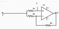
I found this circuit in an old book , I've drawn the circuit .


With :
- F : clock signal 100 Hz
- M is a DC signal from -5 to +5

The author said that the result is M*F.

Please let me know

thanks in advance
Zara
 

DickCappels

Joined Aug 21, 2008
10,152
Please use a more description title next time.

It is a balanced modulator provided that you switch the non-inverting input to ground with your carrier F. This causes the circuit to switch between inverting and not inverting the signal as a function of the state of F.

Among other things, the swich can be a transistor if the base drive swings far enough below ground so that the collector-base junction does not become forward biased, with a MOSFET provided the capacitance is not to high, it can be a transmission gate (such 74HC4066) or a microcontroller out pin switched between being high impedance and ground if the signal is only a few hundred millivolts.

R2 and R3 should be equal.
 

MikeML

Joined Oct 2, 2009
5,444
I have used that circuit as a synchronous detector (also known as a synchronous demodulator). Typically, you set the gain of the opamp to alternate between +1 and -1 as a function of the "carrier", which is a square wave with a 50% duty cycle.
 

Thread Starter

Zara Engineer

Joined Feb 6, 2015
53
Hi guys
thanks for help
and sorry for mysterious title :)
but until now, i didn't understand by equation how can we have an output equal to F*M ? or F*Vin

I tried to put per example M = 0 ;
F = V+ = V-
that's mean that (0-F)/R2 = (F-Vout) /R3;

R2 = R3 = R;
=> Vout = 2 * F; ??
and about you it's F*M=F*0 = 0 ;

Please let me know what's the equation of output ! and an example please .
Thanks in advance.
Zara
 

MikeML

Joined Oct 2, 2009
5,444
F is equal to + or -C, where C is a constant, like 1 or 1.345. It is not a true multiplier where C can be varied dynamically. (C cannot be a function of time)
 

joeyd999

Joined Jun 6, 2011
5,237
I have used that circuit as a synchronous detector (also known as a synchronous demodulator). Typically, you set the gain of the opamp to alternate between +1 and -1 as a function of the "carrier", which is a square wave with a 50% duty cycle.
And I use the analogue in the digital realm for digital synchronous detection.
 

MikeML

Joined Oct 2, 2009
5,444
Here is how to implement that function using an opamp. The switch shown is usually replaced with a FET. Note that the switch is closed when V(F)>0V; and is open when V(F)<=0V.

Can you see how the switch reconfigures the opamp so that its gain goes from +1 to -1?

186s.gif
 
Top