Identifying oscillator circuit on ti 84 plus ce.

Thread Starter

thyking7

Joined Mar 17, 2025
5
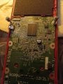
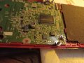
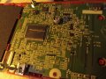
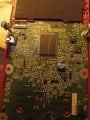
I'm trying to find the oscillator circuit in a ti 84 plus ce, and the oscillator is integrated inside an ASIC with ram and cpu, but there would be a circuit that leads out of it. I've tried voltage testing the test points and frequency testing, but there's many voltages that match and the frequency is too high for most multimeter. I'm planning on cutting the lane and putting in a new oscillator. Please help me identify it.
 

0ri0n

Joined Jan 7, 2025
167
The crystal, in a small TC-38 cylindrical case, lying down on the PCB and glued to it, is placed below the main chip. Above the crystal are the rest of the passive parts seen in every standard Pierce oscillator circuit, two loading capacitors, a series and a bias resistor . Between the passive components are two vias (I/O) that make the connection to the inverting gate inside the main chip.
 

Thread Starter

thyking7

Joined Mar 17, 2025
5
The calculator I have is an L model which is the newest model with the newest ti OS. This one has a JB-007-00 ASIC which contains the ram cpu and crystal, I've seen the older models in pictures and videos with the oscillator separate, but I can see the model numbers on the back of the ti 84 plus ces that I see for sale (and i dont have enough money). But I'd assume that there's an external circuit that the frequency would have to flow through like micro capacitors or resistors or something. But I can't find it because the frequency is way to high and half the other pathways have the same 3.3v that supplies the crystal.

Sorry about the picture quality.
 

Attachments

0ri0n

Joined Jan 7, 2025
167
The calculator I have is an L model which is the newest model with the newest ti OS. This one has a JB-007-00 ASIC which contains the ram cpu and crystal
If a crystal is used it will not be inside the ASIC. Danko already showed you where the crystal (black case) is, the "X" in the reference designator is a dead giveaway. Left and right of the crystal (X01D) are the loading caps (C03D, C04D). Above the crystal you can find the series resistor (R06D), the bias resistor (R01D) and two traces leading to the ASIC.
 

Thread Starter

thyking7

Joined Mar 17, 2025
5
Thank you, sorry I'm new with circuits alone, this is a big help, I was thinking I would have to inject a new frequency through like the debut test point. Thank you. : )
 

Thread Starter

thyking7

Joined Mar 17, 2025
5
Thank you soo much, I'm new to working with circuits. I thought I was going have to inject the frequency through a debug test point.
 
Top