Facebook
 Google
 GitHub
 Linkedin
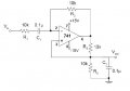
Please can anyone find the gain for this circuit? i have uploaded the circuit and this is a link also : http://s000.tinyupload.com/?file_id=04863447381340379754
Please can anyone find for me the Gain?
- Thread starter student111111
- Start date