Please advise or Spec me a circuit...

Thread Starter

dbov22

Joined Aug 28, 2012
24
Righto...soldered in place the first series then went to test the series...
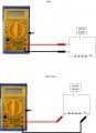
Hooked up multimeter in the 10A mode and when I touch the probes on the circuit I get a little spark from the +ve probe and the LEDs go off and the numbers change on the meter every approx half second and the common numbers seem to be 22, 55, 130,85, 171 etc in no particular order...

When I connect meter in 200m mode....LEDs stay on and I get no reading at all on meter screen

The LEDs come back on as soon as probes are removed, I followed advice to the letter from elec mechs picture. Also, I have checked the fuse inside the meter...there is one fuse and it's fine...
 
Last edited:

elec_mech

Joined Nov 12, 2008
1,500
The LEDs come back on as soon as probes are removed,
If that is true, then something isn't hooked up correctly. The meter should be in series with the circuit - as soon as either probe is removed, the LEDs should go off because there is no longer power flowing through the circuit.

With your power supply hooked up but disconnected from the wall, could you reconnect everything again with the meter and take a picture?
 

Thread Starter

dbov22

Joined Aug 28, 2012
24
the longer wires to left of board are LED's connecting to resistor - the proper board will be neater than this, this is just incase i need to remove resistors...anyway..here is the photo as requested...


By squeekybean at 2012-09-05
 

elec_mech

Joined Nov 12, 2008
1,500
Okay, it looks like you're connecting the meter in parallel as you would do to measure voltage or resistance. This will cause a short and explains the sparks you saw earlier.

Look closely at the current measuring instructions I posted earlier. To measure current, the meter has to be hooked in series with the circuit.

I've attached a quick drawing showing the difference. The bottom image is what I *think* you are doing.

Also note to get an accurate measurement you'll need to have the other LED strips disconnected/desoldered so you're only measuring the current going to one set of LEDs, not multiples. It will probably be easier to quickly solder up a set of LEDs and a resistor separate from your board and take the measurement that way - just be sure you set the circuit on a non-metallic/non-conductive surface so you don't short it out.
 

Attachments

Thread Starter

dbov22

Joined Aug 28, 2012
24
elec mech, yeah, you were right...i was linking it up in paralell...

however I wired up exactly in series and still got no reading whatsoever..maybe my multimeter is broke (it is a really really cheap one that was included in an electronics basics kit)

I have made 2 panels so far, and in both panels i have the odd LED that flickers or will not light....I have changed the LED and that particular position still wont light or flickers, after removing the LED i tested it and it's fine...

hmm
 

elec_mech

Joined Nov 12, 2008
1,500
..maybe my multimeter is broke
Check the fuse first. If that is good but the current reading still doesn't work, may be time to invest in a new meter - if this is a one time project it may not be worth it, but I leave that to you.

I have made 2 panels so far, and in both panels i have the odd LED that flickers or will not light....I have changed the LED and that particular position still wont light or flickers, after removing the LED i tested it and it's fine...
Hmm, could do a quick drawing or schematic of how you have them wired up including total number of LEDs, resistor value, and voltage from supply? Provide a voltage measurement with the LEDs on if possible. Be sure to test only one strip/circuit at a time, not both at the same time for now.

We'll need more info, but this could be due to a number of things:
1) Bad LEDs - either the one flickering, which you've replaced, or others on the same strip (unlikely, but possible).
2) Short on the board somewhere.
3) Bad resistor acting as short (could've got cooked when you hooked up your meter that last time).
4) Too many LEDs relative to the voltage source.
5) Improper resistor value.
 

Thread Starter

dbov22

Joined Aug 28, 2012
24
I will invest in a new meter, I also think I need to use something other than strip board....maybe matrix board where there are no copper strips would be better as I am having to cut the strips where needed to prevent any current flowing...and these cuts might not be good enough...I have made the 2 panels exactly the same as my hand drawing a few posts back... All of the first +ve LEDs are connected to the +ve lead from PSU then there are a total of 4 LEDs connected in series to a 270ohm resistor. All of the last legs from the resistors are joined to the -ve cable from PSU.
 

Audioguru

Joined Dec 20, 2007
11,248
I cut the strips of copper on stripboard with a drill bit at a hole where there is no wire. Zip and the strip is cut neatly.
The drill bit does not cut through the board.
 

Audioguru

Joined Dec 20, 2007
11,248
The RadioShack breadboard is the one with the intermittent contacts and has too much inductance and capacitance so that many circuits DO NOT WORK.
 

elec_mech

Joined Nov 12, 2008
1,500
The RadioShack breadboard is the one with the intermittent contacts and has too much inductance and capacitance so that many circuits DO NOT WORK.
I just found something quick and readily available, although I forgot the OP isn't in the U.S. The local electronics shop should have these though.
 

Thread Starter

dbov22

Joined Aug 28, 2012
24
I got a breadboard and tried out my meter... In the 10amp setting I get a reading of 0.02 and if I use a 470ohm resistor I get a reading of 0.01... In the other '200' mode on the meter I get no reading whatsoever... Does this confirm meter is broken? The fuse is fine inside.

Ps. Went to make first proper panel and soldering iron packed up and won't now heat up...grr
 

elec_mech

Joined Nov 12, 2008
1,500
If the fuse is good but you're not getting a reading when the meter is set to 200mA, then that portion of the meter may be toast. Since you didn't sound like you treasured the meter to begin with, it's probably a good idea to replace it with a better one.

When you say you measured 0.02A with the 10A meter setting, did you have a resistor in series with the LED (I hope)? If yes, what was its value?

How many LEDs were connected in series or did you just test one?

Ps. Went to make first proper panel and soldering iron packed up and won't now heat up...grr
Might be time for a new soldering iron too. :D
 

Thread Starter

dbov22

Joined Aug 28, 2012
24
Yes the meter was definitely in series with the LEDs. I had 4 LEDs in series initially with a 150ohm resistor then also with a 300ohm resistor then a 470ohm, there was little difference in brightness between 150 and 300 but noticeable difference with the 470.

Elec mech, I am confused at which value you wanted to know... The only reading I could get was on 10A setting was 0.02 with a 150ohm then separately a 300ohm resistor (am I correct in thinking this is a current of anywhere between 20-29mA?)

With the 470ohm resistor I could only get a reading of 0.01 (am I correct
in thinking this is anywhere between 10-19mA?

I have ordered a new multimeter and a new soldering iron!
 

elec_mech

Joined Nov 12, 2008
1,500
Ah, I wasn't sure you had tried multiple resistors and got the same reading. If the reading is 0.02A on the 10A scale, this could mean the actual current is somewhere between 0.015 - 0.024A. For 0.01A, the actual current could be 0.005 to 0.014A.

Generally speaking, it is common practice to round up to the next highest value when the preceding value is 5 or higher. I can't explain this well, but I can show examples.

If you're limited to two decimal places and the measured value is 0.025A, then the meter will show 0.03A. If the measured value is 0.024A, then the meter will show 0.02A.
 

KJ6EAD

Joined Apr 30, 2011
1,581
In the 10amp setting I get a reading of 0.02 and if I use a 470ohm resistor I get a reading of 0.01... In the other '200' mode on the meter I get no reading whatsoever... Does this confirm meter is broken? The fuse is fine inside.
It still sounds like a blown low current fuse. How did you test it?
 
Last edited:

elec_mech

Joined Nov 12, 2008
1,500
Both meters will work well. The smaller meter seems to be able to measure smaller currents which could be helpful. The smaller one can measure resistances up to 20MΩ while the larger one can go up to 200MΩ. Both handle the same voltage ranges in AC and DC. Personally, I think the smaller one will work just fine and I like the smaller current measurements it can do. I use something similar for 90% of the things I test.
 
Top