Please advise or Spec me a circuit...

Thread Starter

dbov22

Joined Aug 28, 2012
24
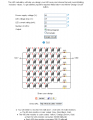
Hi, i would imagine this will be simple for most of the people on this forum. I made an LED panel containing 40 LED's and powering it using a transformer from an old garden light set.

On another forum (not specifically for electronics) I have been given masses of differing advice ranging from "the LED's will blow as soon as you plug it in" to Some will light up brighter than others" and finally "that is a terrible circuit - you need 1 resistor per LED".

Now, just quickly, the LED panel I made has been on for 6 hours and every LED is bright, evenly lit and has not burned out)

Rather than show you what I have done so far, can someone spec me a circuit - simple drawings will do to make the following design.

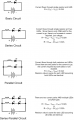
I have 4 transformers at my disposal so if you could tell me which is best to use, that'd be great!

I want to use white LED's


By squeekybean at 2012-08-28


By squeekybean at 2012-08-28


By squeekybean at 2012-08-28


By squeekybean at 2012-08-28


By squeekybean at 2012-08-27
 
Last edited:

elec_mech

Joined Nov 12, 2008
1,500
Hi dbov22,

There are any number of ways to do this. I'd suggest reading Bill's blog first to get yourself more familar with LEDs and how to power them: http://forum.allaboutcircuits.com/blog.php?b=378.

The first three power supplies appear to have AC output. While it may be possible to power LEDs with AC, I'm only familar with DC which is the last power supply pictured.

You have 40 white LEDs which are generally rated 3.6 to 3.7VDC and assuming these are standard 5mm, your current requirement will be about 20mA per LED. Total, you will need a power supply capable of 40 x 3.7 x 0.02 = ~3W. Since the last supply is rated up to 5W max., this should do it.

If you know the voltage and current of the LEDs and it is not close to what I have mentioned above, stop here and let us know.

I assume all LEDs will be on at the same time? If so, I'd hook up two in series which will require 2 x 3.7V = 7.4VDC. Using the last supply rated at 12VDC -> 12-7.4 = 4.6V. Using Ohm's law: V = IR -> 4.6 = 0.02 x R -> R = 230Ω. I'd suggest using a 270Ω resistor or whatever you have that is close to that and put it in series with the 2 LEDs. Repeat for the rest giving you 20 sets of two LED in series. Connect these 20 sets in parallel and connect to your 12VDC power supply. Each set will require 20mA, so 20 x 20mA = 400mA. Your supply is rated 5W/12V = 417mA, so you'll be close to the max rating of your supply and it may get warm, but you should be okay.

Again, there are multiple ways of doing this, this is just one.

If you could post a schematic of what you have done we can offer advice or provide more information.

Lastly, note this is an international forum so it may take time to get a response.
 

Thread Starter

dbov22

Joined Aug 28, 2012
24
Right, good point, I hadn't even realised they were AC adaptors - (doh)

OK - this is what I did, I am aware it is deemed wrong by many people so not looking for too much feedback on why it's wrong. I just need to know how to do this correctly and so that all the LED's are as bright as they can be, even if it means buying a better DC transformer from Amazon UK.


By squeekybean at 2012-08-27


By squeekybean at 2012-08-27

please remember - I am a total beginner, this was a test to see if it worked. The LED's used are 3.4 Vf 0.022A White colour.
 

elec_mech

Joined Nov 12, 2008
1,500
What is the voltage and current (or power - wattage) of the supply you are using for your pictured test circuit?

First, nice job on the diagram and your circuit. Very clean. It will need to be modified to work long-term - I understand you're new to this, so please understand this isn't meant to be mean or spiteful. You've asked for help and that's what we're here for. :)

So when working with LEDs, it is important to limit the current going to them otherwise they'll take in too much and eventually, if not immediately, burn out. You do this by including a current-limiting resistor in series with one of the LED's legs; it does not matter which one.

I didn't get into a lot of details with my suggestion, so let me elaborate. If you put LEDs in series, you add up the voltages of each LED to get the total required voltage to drive them. This also means one current path for the set and thus only one resistor is needed to be placed in series with the set.

You generally work backwards by first starting with the available power supply(-ies) you have available. In this case, I only saw one DC supply and chose it. It is rated at 12V. So, if I put two LEDs in series, I need at least 3.4 x 2 = 6.8V to drive them. Remember you must have a current-limiting resistor, so that means you'll need some overhead - in other words a higher supply voltage. You wouldn't, for example, use a 6.8VDC supply if you could find one.

So, 12V-6.8V = 5.2V. Since your LEDs need 22mA, you need V = IR -> R = 5.2/0.022 = 236Ω or a commonly found 270Ω resistor in series with the two LEDs to act as a current limiter.

Now, you could put three LEDs in series and:
3.4 x 3 = 10.2V
12V - 10.2V = 1.8V
1.8V/0.022A = 82Ω (a commonly found value)

Of course, 3 LEDs in series means you'll have 13 sets of LEDs and one by itself meaning the one left will need its own resistor: 12-3.4/0.022 = 390Ω. The advantage to three is you'll require less current from your supply: 13 + 1 = 14 x 0.022A = 0.31A vs. 20 x 0.022 = 0.44A.

Unless you're running off batteries or your supply cannot provide enough current, putting two in series for a total of 20 sets with 20 identical resistors is probably easier.

I've drawn a quick schematic showing how to wire two LEDs in series and three for your application. I think the 12VDC supply you pictured will work quite nicely for either option. Hopefully this helps.

You can probably drive the LEDs with a higher current, usually 30mA is the max, if you need them brighter still. Just look at the calculations above and replace the 0.022 with 0.03 to get the new resistor values.

Let us know if you have any questions.
 

Attachments

Thread Starter

dbov22

Joined Aug 28, 2012
24
Elec-mech. Thank you for that reply, it made a lot of sense. The transformer I used was the 12v one you used in your calculations. However it is a 5w transformer and apparently will not power the circuit I have in mind. So without sounding cheeky, can you please explain how it is fine to use that exact transformer pictured? More for my own understanding.

You truly have made it a lot easier to understand and I really thank you for it!!!

Ps. I think I am getting this now, a total of 70 LEDs running at their brightest (3.7) x the current they'll draw 0.02 equals a total wattage of 5.18w so this is over what the transformer can handle so it'll still work but will probably get quite hot but still work?

Thanks mate
 
Last edited:

Thread Starter

dbov22

Joined Aug 28, 2012
24
I have found a DC 12v 5A 60w transformer on eBay. This will more than cover the consumption of the LEDs won't it. Like in theory, I could safely power 1 single LED from this transformer provided I used the correct resistor?
 

wayneh

Joined Sep 9, 2010
17,498
... I could safely power 1 single LED from this transformer provided I used the correct resistor?
Yup, that's right. :)

But does it include a filter capacitor? This would be a good idea, to reduce the ripple coming out of the rectifier.

Maybe the LED gurus here can comment. It seems to me that a rippling supply - while supplying some average current to the LEDs - will shorten the life of those LEDs, compared to a steady voltage, because the repeated peaks above average will do damage over time. That said, I guess the effect is minimal unless you're running near peak.
 

elec_mech

Joined Nov 12, 2008
1,500
However it is a 5w transformer and apparently will not power the circuit I have in mind. So without sounding cheeky, can you please explain how it is fine to use that exact transformer pictured?
Do you mean the 70 LEDs or the 40? You originally said 40, so this is what I was basing my calculations on.

You are correct, the 5.18W will really push the 5W transformer. If you want to use it to test your circuit for a minute or two, you should be fine, but I wouldn't use it for more than that.

The 60W sounds like a winner. As wayneh already mentioned, yes it will power a single LED as long as you use the right resistor.
 

Thread Starter

dbov22

Joined Aug 28, 2012
24
Just to test my Maths
In the panel prototype I made I had 6 rows of 6 LEDs if the LEDs are 3.4-3.7 I'll work off 3.5. 3.5v x 6 = 21v I have 6 strips of these does this mean the LEDs are actually dimmer than they should be?

Elec mech - sorry yeah, my aim is to have 70 LEDs so ignore my most recent comment to you as its clear you've based your calculations on 40 which was what I made. But want to make basically 5 individual panels totalling 70 LED.

WaNye - I don't know if it has a filter capacitor - eBay mentions nothing about it... here's the link http://www.ebay.co.uk/itm/270953964030?ssPageName=STRK:MEWAX:IT&_trksid=p3984.m1423.l2648
 
Last edited:

wayneh

Joined Sep 9, 2010
17,498
Ah, yes, a laptop power brick. It's not the traditional wall-wart plus rectifier, which is where my comment was directed.

That'll be fine. About the only concern I'd have is that the voltage rating may be at significant current draw, and might actually be quite a bit higher at low load. So, I'd check the no-load voltage as well as the voltage at your intended current. Since it's regulated, it's probably quite good but you don't need a surprise. ;)
 

KJ6EAD

Joined Apr 30, 2011
1,581
Just to test my Maths
In the panel prototype I made I had 6 rows of 6 LEDs if the LEDs are 3.4-3.7 I'll work off 3.5. 3.5v x 6 = 21v I have 6 strips of these does this mean the LEDs are actually dimmer than they should be?
You are completely misunderstanding the difference between series and parallel circuits. In the example circuit, all LEDs are exposed to the full supply voltage (in parallel). It doesn't matter what the physical arrangement is; it matters that they are electrically in parallel. The only reason that connecting a bunch of 3.5V LEDs to 12V hasn't destroyed the LEDs is because the power supply is overloaded. If you don't believe me, try measuring the voltage with the 40 LEDs running. It will be around 3V.
 
Last edited:

elec_mech

Joined Nov 12, 2008
1,500
Just to test my Maths
In the panel prototype I made I had 6 rows of 6 LEDs if the LEDs are 3.4-3.7 I'll work off 3.5. 3.5v x 6 = 21v I have 6 strips of these does this mean the LEDs are actually dimmer than they should be?
Yes, the LEDs don't have enough voltage from your supply to properly power them. You seemed a bit shy about getting a formal critique early on, so I've just focused on showing you how to do it right. Having a current-limiting resistor with the proper voltage is of the utmost importance though.

On that note, I've redone my schematic to show you how to do this with 70 LEDs in five sections as you mentioned. You'll need a 12VDC supply rated 2A or higher. Actual consumption is about 0.77A to 1.05A, but it's a good idea to use something with more current so the supply doesn't get too hot. The laptop supply would work well. Hope this helps.
 

Attachments

Thread Starter

dbov22

Joined Aug 28, 2012
24
Ah that's great, thank you, I totally appreciate that I need resistors - going to go any buy all the stuff I need tomorrow.

I think I'm over confusing series and parallel - I can't work out now whether my wiring was series or parallel.

The only reason I didn't ask for a critique was I knew it would be wrong and wanted to know a good way of doing it rather than why mine was bad. Lol.

I really appreciate all the advice and help from you guys!l
 

elec_mech

Joined Nov 12, 2008
1,500
I think I'm over confusing series and parallel - I can't work out now whether my wiring was series or parallel.
It was both as are the examples I used. I just threw the attached picture together to kind of help give you an idea.

I started trying to explain this in better detail, but there is a lot to explain and lots of different ways to explain it. Take a look at the picture and let us know what questions arise.

The only reason I didn't ask for a critique was I knew it would be wrong and wanted to know a good way of doing it rather than why mine was bad.
No problem, the important thing is knowing when to ask for help. We're all here to learn, have fun, and keep safe.
 

Attachments

Thread Starter

dbov22

Joined Aug 28, 2012
24
Yeah, I sorta posted that then it totally clicked, I am getting a much better understanding now of why series is a lot more efficient than parallel. I fully understand why resistors are needed and the difference between series and parallel.

I have ordered some UV LEDs from eBay and I'm going into work this morning to take some old laptop power supplies destined for the bin. I will pick the most appropriate one and then plan the schematic myself, post on here before building it and get expert opinion!

Once again, thank you all very much especially elec mech! It really is fantastic how much you've all helped and appreciate this takes time!
 

Thread Starter

dbov22

Joined Aug 28, 2012
24
Guys, the LEDs I have, have a Vf of 3.2-3.8. I have based my wiring schematic on 3.8. Is that the best thing to do?

I also got a laptop power brick which is DC 19V 65W. If I divide 19v by 3.8 (Vf) it comes back with a straight 5. The LED wizards out there all say this is fine with a 1ohm resistor. Is the resistor even necessary?

The circuit I've drawn up has a series of 4 LEDs with a 150 ohm resistor. Is this better?

So, the questions from today's post;

1. Do I use the highest Vf value as the basis for calculating my resistance?
2. Am I better of using a series of 4 LEDs with a resistor value in the 100's rather than series of 5 LEDs with a 1 ohm resistor?
 
Top