 Facebook
 Google
 GitHub
 Linkedin
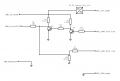
I am trying to make a digital readout for my car. I could not find an OBD readout that would do what I wanted so decided to make my own. My car has a single wire bi-directional serial communication through the OBD2 port called K-Line. The logic level of this serial communication is 0-12V and my microcontroller is 0-3.3V. I was hoping to get some opinions from anyone who might have dealt with something like this to take a look at my schematic before I fry my car's electronics. I am not an electronic engineer as you might be able to tell from my schematic so any advice would be appreciated.
About the circuit:
It is a basic level shifter which converts/shifts the microcontroller's 3.3V logic to 12V in order to communicate with the car's ECU. My car has an ECU -> Some gateway/module -> OBD2 -> My microcontroller. There are two transistors; first (Q1) is connected to the microcontroller's UART TX pin using a 2.1k resistor between. This is because the microcontroller TX pin's idle state is HIGH, when this is high it is meant to make the K-Line high which I believe also has idle state as HIGH. K-Line is kept HIGH or LOW using the transistor Q2. I then have a 1kOhm resistor from the K-Line as a safety. Safety because transistor Q2 shorts the K-Line to GND to make it go LOW when communicating. If this was constantly shorted to ground it would result in a current draw of 12mA (12 V / 1000 Ohms), is that right? Also is 12mA within the threshold for ECU pins generally? Is this a bad idea? I have not been able to confirm if K line is open collector. The 12V supply from the car's OBD2 port supplies the microcontroller with 3.3V using a DC/DC buck converter. The ground is common. For microcontroller UART RX pin, I have used a voltage divider to bring the 12V to around 3.3V. The microcontroller is cheap so I am not too worried about it, my car's electronics are my worry.
Please let me know if you see anything wrong with this circuit and any way to improve it. I could post details about the car's ECU or make if needed. Thank you.
Attachments
-
 27.3 KB Views: 13


